


Introduction
An abrasion tester is used to evaluate the abrasion resistance of rubber. The cut and chip (CC), Lambourn, DIN, and laboratory abrasion tester (LAT100) have been widely used. The CC abrasion tester is a simple and fast test method, and it is designed to evaluate the wear characteristics of rubber compounds under harsh conditions like direct contact with rocks, gravel, and uneven road surface.1-7 Cutting occurs when a specimen is pierced or cut through a surface with sufficient force by a sharp blade. Chipping occurs after cutting and is caused by the effect of traction, braking, or other forces on rough or sharp surface. This usually causes the specimen to tear at a right angle (90°) to the cutting direction. Physical properties of tear and tensile strength, elongation, and modulus can be influencing factors on the CC abrasion test, but it is known that the test is not related to crack or fatigue propagation.3,7
The Lambourn abrasion tester was developed to simulate the deformation of a rotating wheel under a constant load.8-10 Its test is performed using a small disc-shaped specimen and a large abrasive wheel. The specimen and the abrasive axis are rotated at the same time, and the specimen is abraded by slip caused by the difference in rotation speeds between the two axes. Slip is a measure of the severity of wear. Talc powder is sprinkled between the specimen and abrasive to prevent smearing during the abrasion test.
The DIN abrasion tester is one of the standardized tests used to characterize the abrasion resistance of rubber.11,12 It measures the amount of wear while moving a certain distance from right to left after pressing a specimen with a constant load on a rotating abrasive surface drum.8,13 It can be tested while changing the vertical load applied to the specimen. The apparatus and method are simple, and the testing time is short.
The laboratory abrasion tester (LAT100) is a machine which can simulate a wide range of test conditions.14-18 The specimen moves at the specified speed under the set slip angle and load on the flat surface of the abrasive disc. Parameters of slip angle, load, speed, and temperature can be adjusted. During the test, the lateral force of the rubber wheel by the slip angle is measured. Several researches compared the test results obtained by different abrasion testers.19-21 Stocek et al. tested the CC resistance of NR, BR, and SBR rubbers filled with carbon black, and reported that order of the CC resistance was NR > SBR > BR, but the evaluation through DIN wear showed the opposite.20
Tire wear particles (TWPs) discharged into the environment can cause pollution of river and sea through road runoff and rainwater, and can become air pollutants as fine dust in the air when broken into smaller pieces.22-24 It is a potential threat to the health of aquatic and terrestrial organisms, including humans, by distributing in ecosystems. TWPs are mainly found in the range of a few nanometers to hundreds of micrometers.23-25 In actual roads, TWPs are combined with road dust or minerals on the pavement as tire-road wear particles (TRWP).25-27 Previous studies have mainly evaluated the wear performance with the amount of tire wear.28-31
It is necessary to conduct research on the size distribution and shapes of TWPs. Some researches characterized TWPs according to the slip angle and rubber composition using a laboratory abrasion tester.32,33 In addition, change in wear behaviors of rubber compounds depending on aging was characterized by analyzing the properties of wear particles.34 This study aimed to investigate difference in the wear behaviors of an SBR compound depending on the abrasion testers. Size distributions and shapes of the wear particles were analyzed, and morphologies of the worn surfaces were also examined.
Experimental
Silica-filled SBR compound (SBR 1712 = 123.5 phr, silica = 80 phr, silane (X-50S) = 8 phr, other ingredients = 20 phr) was used for preparation of the abrasion specimens. Four abrasion testers of CC, Lambourn, DIN, and LAT100 abrasion testers were employed. Cut and chip abrasion tester of CC-2020 (Myungji Tech Co., Republic of Korea) was used. Size of the specimen is 50 mm outer diameter, 13 mm inner diameter, and 13 mm thickness. Rotation speed of the sample was 750 rpm and the chipping speed was 60 rpm. Width of the chipping blade is 6 mm. Two specimens were tested for 10 min each. Lambourn abrasion tester of AB-1165 (Ueshima Seisakusho Co., Japan) was used. Dimension of the specimen was 49 mm outer diameter, 23 mm inner diameter, and 10 mm thickness. Speeds of the sample and abrasive wheel were 50 and 40 m/min, respectively, and the slip ratio was 19.7%. The load was 44.8 N and the chamber temperature was 35°C. The outer diameter of the abrasive wheel was 175 mm and the width was 25 mm. 80 grit sandpaper was attached to the abrasive wheel. Talc was introduced with the minimal injection level. Each specimen was tested for 10 min.
DIN abrasion tester of WL210A (Withlab Co., Republic of Korea) was used. Size of the abrasion specimen is 16 mm diameter and 8 mm thickness. Diameter of the drum surrounded by 60 grit sandpaper was 150 mm and the rotation speed was 40 rpm. When the test is started, the specimen is moved 40 m from right to left of the tester on the rotating abrasive drum. Two specimens were abraded for 3 min each. LAT100 tire tread compound tester (VMI group, the Netherlands) was used. Size of the abrasion specimen was 80 mm diameter and 19 mm thickness. Electro Corundum Disc Grain 60 of VMI group (the Netherlands) was used as the abrasive disk. The load force was 75 N and the slip angle was 3°. The abrasion test was conducted for 1 h and the velocity was 25 km/h.
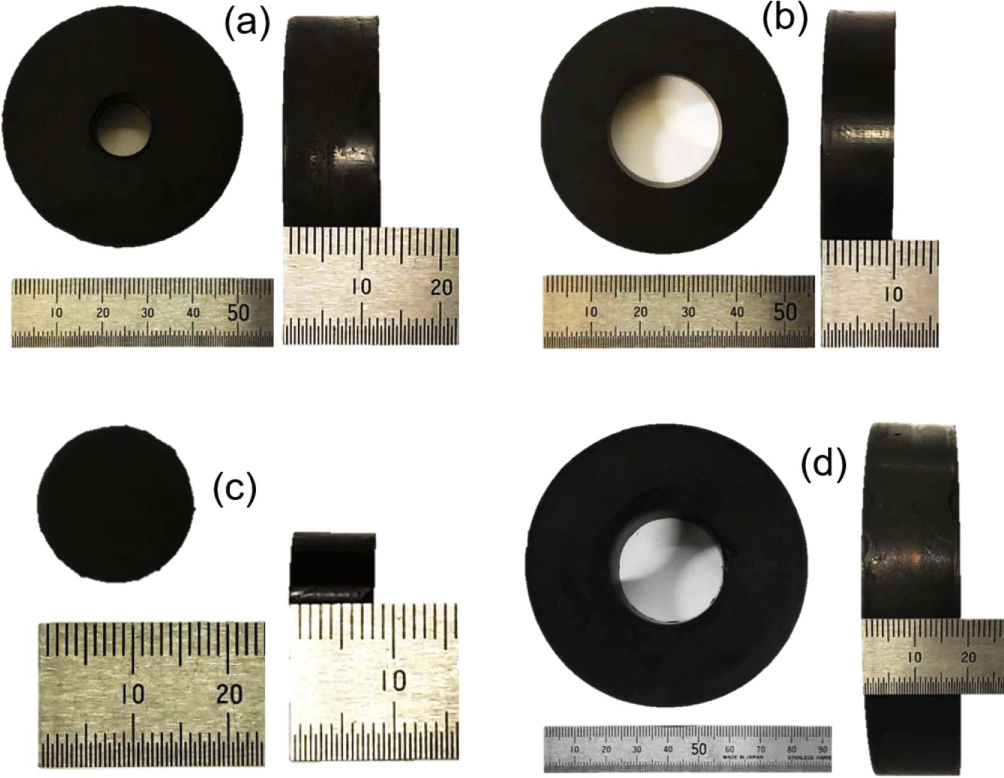
The wear particles generated by each tester were collected and separated by size using a sieve shaker of an Octagon 200 (Endecotts Co. UK). The standard sieves of 1000, 500, 212, 106, 63, 38, and 20 μm were used. Shapes of the wear particles were observed using an image analyzer (EGVM35B, EG Tech Co., Republic of Korea). Photographs of the abrasion specimens for the CC, Lambourn, DIN, and LAT100 abrasion testers were shown in Figure 1.
Results and Discussion
Size distributions of the wear particles produced through the four abrasion tests were summarized in Table 1 and Figure 2. Most of the wear particles had large size (> 1000 μm). Size of TWPs found in real road was usually less than 500 μm.26,35-37 Ratios of the wear particles larger than 500 μm produced from the CC, Lambourn, DIN, and LAT100 abrasion testers were 99.6, 68.0, 96.6, and 96.8%, respectively. Order of the size distribution of the wear particles larger than 1000 μm according to the types of abrasion testers was CC > LAT100 > DIN > Lambourn, while that of the wear particles larger than 500 μm was CC > LAT100 ~ DIN ≫ Lambourn. For the wear particles of 500-1000 μm, the size distribution order was DIN > CC ~ LAT100 ≫ Lambourn.
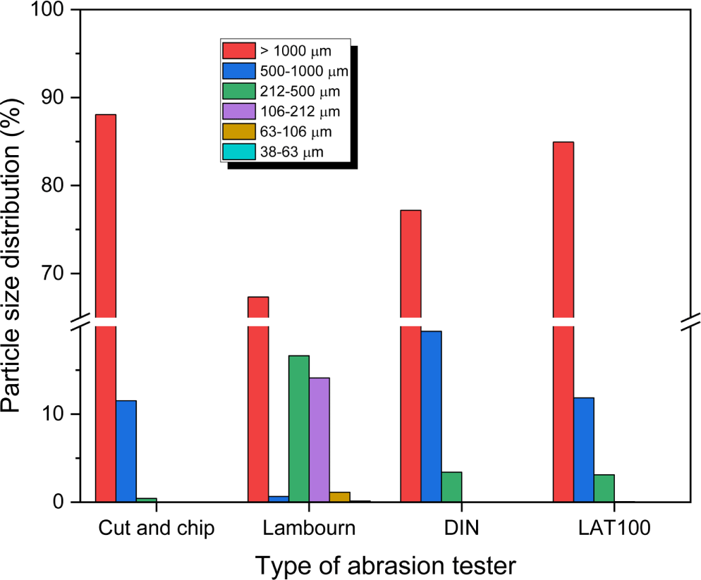
The wear particle size distributions tended to decrease as the particle size decreased. For the CC, DIN, and LAT100 abrasion tests, the wear particle size distributions were steeply decreased by decreasing the particle size. The wear particle size distribution for the Lambourn abrasion test showed decreasing trend with decrease in the particle size, but size distribution of the wear particles of 500-1000 μm was much lower than that of 212-500 μm, even lower than that of 63-106 μm.
Except for the Lambourn abrasion test, the wear particles smaller than 212 μm were rarely generated by the other three abrasion tests. This implies that small wear particles are produced through friction by introducing mineral particles (talc). There are a lot of mineral particles in real road.38-41 Hence, introducing mineral particles for abrasion test leads to not only fast abrasion rate but also reflection of real road conditions.
Abrasion rate is affected by the abrasion test conditions as well as type of the abrasion tester. In this study, the same unit of abrasion rate was employed to examine the difference among the abrasion tests. Abrasion rates according to the four abrasion testers were summarized in Table 2. The abrasion rate for the CC abrasion tester was much larger than those for the others. This should be due to difference in the abrasion tools. A blade is used for the CC abrasion tester as the abrasion tool, whereas an abrasive or sandpaper is employed for the others. For the CC abrasion test, the wear particles are produced by direct impact on the specimen by a sharp blade. For the Lambourn, DIN, and LAT100 tests, the wear particles are formed by friction between the specimen and the abrasive. For the three abrasion testers using an abrasive, order of the abrasion rate was DIN > Lambourn ~ LAT100. For the Lambourn and LAT100 abrasion test methods, the abrasion rates can be controlled by changing the testing conditions such as introduction rate of talc for the Lambourn abrasion test and variations of the load and slip angle for the LAT100 one.
| Cut and chip | Abrasion tester | ||
|---|---|---|---|
| Lambourn | DIN | LAT100 | |
| 152 | 64 | 91 | 62 |
Morphologies of the wear particles were analyzed using the magnified images. Magnifications of the wear particles of > 1000, 500-1000, 212-500, and 106-212 μm were 40, 150, 300, and 300, respectively. Figure 3 shows magnified images of the wear particles produced from the CC abrasion test. The surface was rough and angular because a sharp blade directly hit the specimen. The aspect ratios were relatively small. There was no big difference in the morphologies depending on the wear particle sizes. Figure 4 shows magnified images of the wear particles produced from the Lambourn abrasion test. The wear particles were covered with talc particles and had stick-like shapes. The surface was relatively smooth and the aspect ratios were relatively large. The wear particles larger than 1000 μm had linear stick shapes. For the wear particles of 500-1000 μm, the wear particle with branched structure was found.
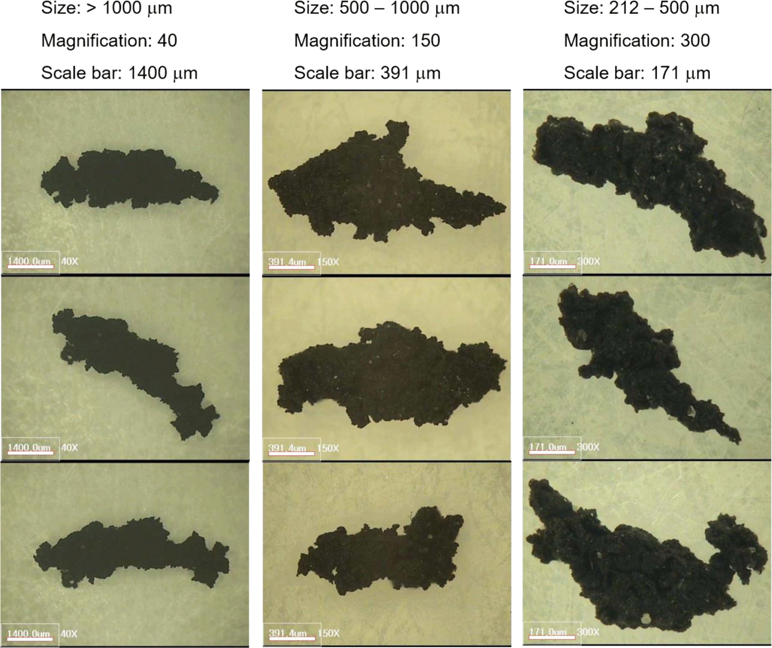
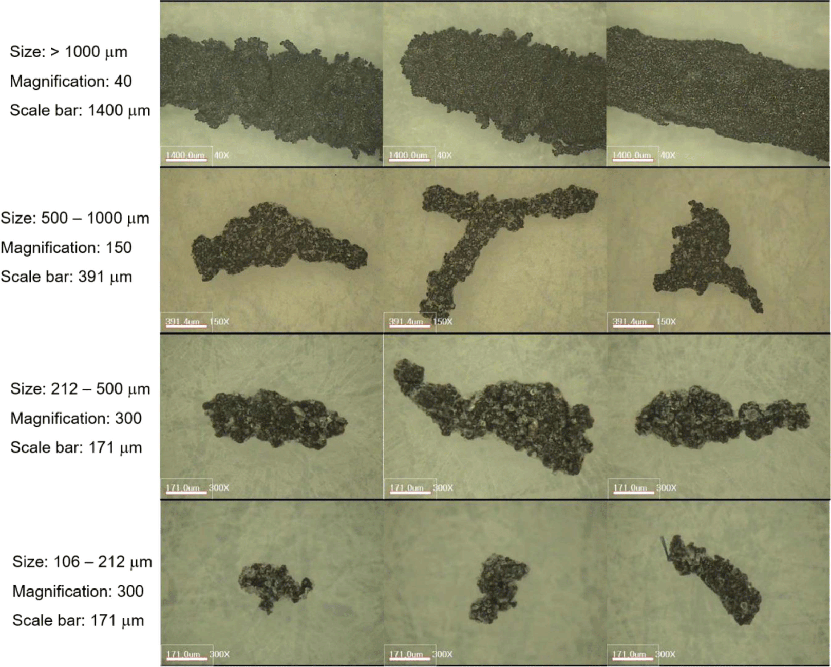
Figure 5 shows magnified images of the wear particles produced from the DIN abrasion test. The surface was relatively rough. For the wear particles larger than 500 μm, some branched structures were found. The aspect ratios were various and tended to decrease as the particle size decreased. For the wear particles of 212-500 μm, there were some tiny inorganic particles on the surface. These inorganic particles should be come from the abrasive matrix. During the abrasion test, the abrasive particles bonded to the matrix are abraded by friction with the rubber sample to generate smaller abrasive wear particles. Some of the abrasive wear particles can be stuck to the specimen surface. Figure 6 shows magnified images of the wear particles produced from the LAT100 abrasion test. The surface was relatively smooth. For the wear particles larger than 1000 μm, some wear particles had branched structures. The aspect ratios were relatively low. Some inorganic particles were stuck on the surface of the wear particle. For the wear particles of 212-500 μm, there was the wear particle covered with inorganic particles. The inorganic particles come from the abrasive matrix showed various sizes.
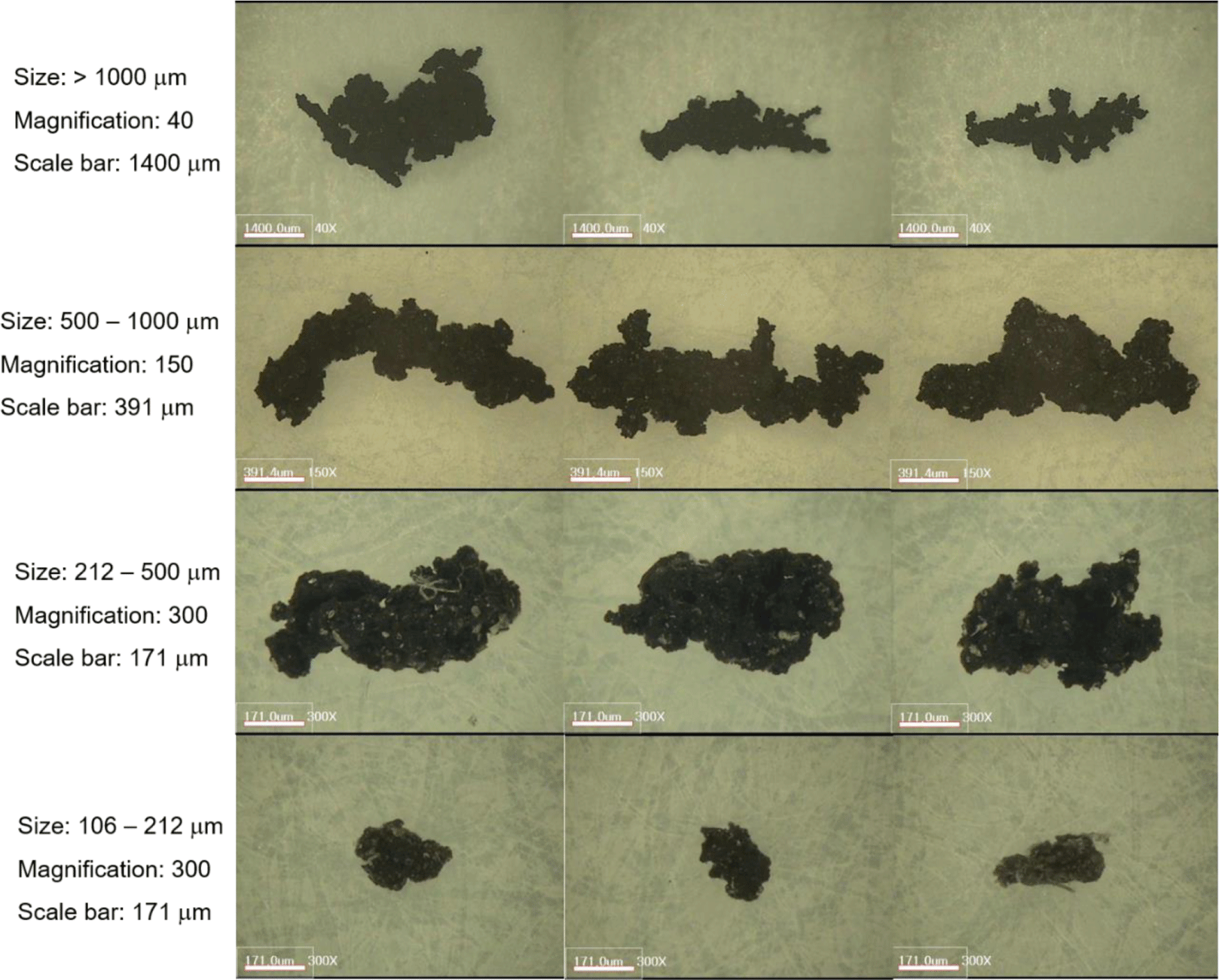
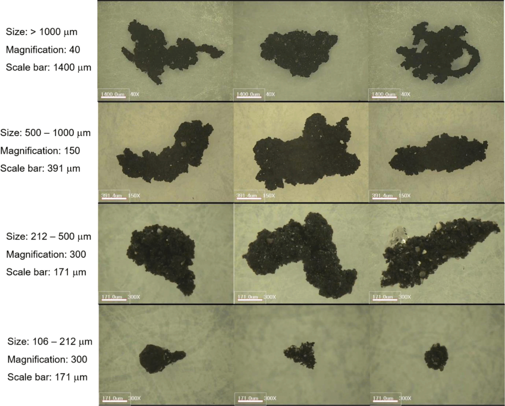
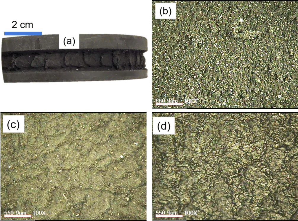
Figure 7 shows the worn surfaces of the abrasion specimens after the abrasion tests. The worn surface obtained from the CC abrasion test showed clear abrasion pattern of the abrasion spacing with 1 cm interval. The worn surface obtained from the DIN abrasion test did not show any specific abrasion pattern, but there were some inorganic particles on the worn surface. This means that many abrasive wear particles produced during the DIN abrasion test were stuck onto the abrasion specimen. The worn surface obtained from the Lambourn abrasion test showed clear but irregular abrasion patterns, and the abrasion spacing was 100-500 μm. There were a lot of talc particles on the worn surface. The worn surface obtained from the LAT100 abrasion test showed irregular abrasion patterns, and it was hard to find the abrasive wear particles on the worn surface.
Conclusions
Most of the wear particles were larger than 1000 μm regardless of the abrasion testers. Size distributions of the wear particles larger than 500 μm produced from the CC, Lambourn, DIN, and LAT100 abrasion testers were 99.6, 68.0, 96.6, and 96.8%, respectively. Order of the size distribution of the wear particles larger than 1000 μm was CC > LAT100 > DIN > Lambourn, while that of the wear particles of 500-1000 μm was DIN > CC ~ LAT100 ≫ Lambourn. The wear particle size distributions tended to decrease as the particle size decreased. Except for the Lambourn abrasion test, the wear particles smaller than 212 μm were rarely generated. Introducing mineral particles for abrasion test can lead to not only fast abrasion rate but also reflection of real road conditions. The abrasion rate for the CC abrasion tester was much larger than those for the others. The wear particles produced from the CC abrasion test had rough and angular surface, while those produced from the Lambourn abrasion test were covered with talc particles and had stick-like shapes. The wear particles produced from the DIN abrasion test had relatively rough surface, while those produced from the LAT100 abrasion test had relatively smooth surface and some inorganic particles were stuck on the surface. The worn surface obtained from the CC abrasion test showed clear abrasion pattern, but that obtained from the DIN abrasion test did not show any specific abrasion pattern. The worn surfaces obtained from the Lambourn and LAT100 abrasion tests showed irregular abrasion patterns.