Introduction
The development of high-speed communication technologies, including 5G and beyond, is crucial to meet the demands of various information technology (IT) devices.1,2 With the increased use of millimeter-wave frequency bands in 5G+ technology, the demand for IT devices requiring high-speed and high-capacity data processing, such as wired and wireless network equipment, supercomputers, and semiconductor testing equipment, is rapidly increasing.3-7 However, because high-frequency signals travel over short ranges, the quality of printed circuit boards (PCBs), which are essential communication circuits, is vital for minimizing signal degradation and ensuring high-speed signal processing.8-11
PCBs consist of various electronic components integrated into a circuit that transmits signals and commands.12 A PCB generally features a laminated structure composed of composite materials that maintain its shape and physical properties as well as copper foil to form the circuits for transmitting and receiving electrical signals.13 The materials in the composite are polymer substrates, fillers, and glass fibers. Especially for 5G applications, to prevent signal delay and loss, polymer substrates with excellent low-dielectric properties14 and fillers or glass fibers with superior electrical properties,15-19 low moisture absorption,20 and high-temperature dimensional stability21-23 are essential. Representative polymer materials with excellent low-dielectric properties used for high-speed telecommunication applications include polytetrafluoroethylene (PTFE),24 polyimide (PI),25 polypropylene (PP),26 and liquid crystal polymers (LCP),27-29 all of which typically exhibit low dielectric constants of 2.1 to 2.9 and low dielectric loss rates of 0.0001–0.002.30,31
As mentioned earlier, the performance of low-dielectric materials is a key factor in determining the performance of the substrates, resonators, filters, and antennas used in high-frequency devices. In particular to minimize signal loss at high frequencies, materials with low dielectric loss (tan δ or loss tangent) are required. With the advancement of high-speed communication technology, research on new materials that satisfy the requirements of low dielectric loss is actively underway.32-34 This study aims to explore the potential application of these materials in 5G PCBs by manufacturing films using silica fillers with low dielectric loss. Specifically, we investigated the optimal ratio of polydimethylsiloxane (PDMS) to silica fillers and the composite materials that achieved low dielectric loss. The composites developed in this study are expected to be key materials that can meet the requirements of high-frequency applications, particularly in 5G and next-generation communication technologies.35,36
Experimental
The polydimethylsiloxane used in the composite was produced using a Sylgard 184 kit (Sylgard 184 silicone elastomer, Dow), which consists of a pre-polymer and a cross-linker that can be thermally cured at room temperature. The pre-polymer and cross-linker were mixed at a 10:1 ratio. The fillers used in the composite were two types of magnesium silicate powder (Mg2SiO4) with different particle sizes (MS5000, and MS1000, Sukgyung AT Co., Ltd).
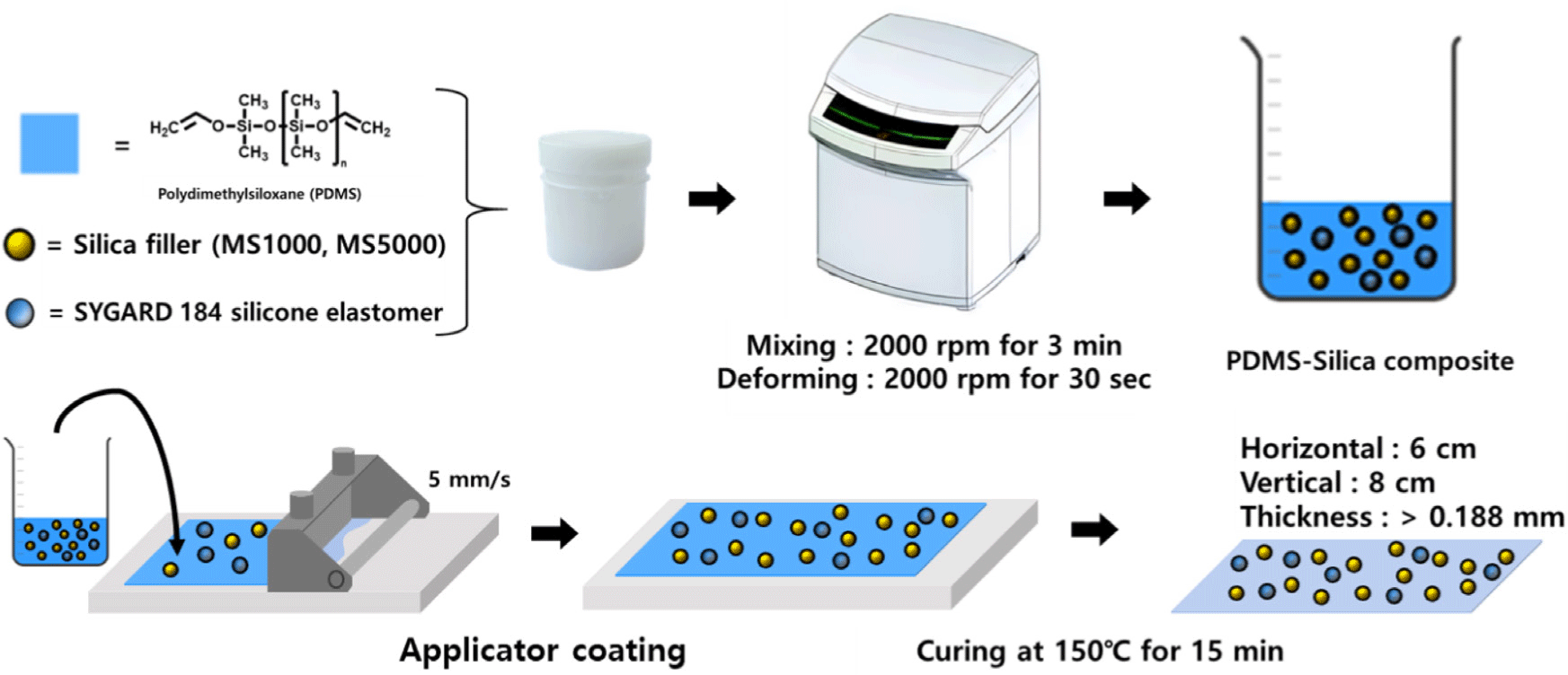
A resin solution was prepared by mixing the PDMS prepolymer and cross-linker at a 10:1 ratio in a high-viscosity mixer container (Figure 1). Silica particles were then added at concentrations of 10–60 wt%. The PDMS and silica mixture were mixed using a high-viscosity mixer (ARE-310, Thinky) at 2000 rpm for 3 min. Following mixing, a defoaming process was conducted at 2200 rpm for 30s to remove bubbles. To eliminate any bubbles remaining in the mixture, it was placed under vacuum for 30 min. The final bubble-free mixture was coated onto a release liner using blade-coating at a speed of 5 mm/s with a thickness of 0.3 mm. The PDMS–silica composite film on the release liner was then cured in an oven at 150°C for 15 mins, and the cured film was peeled off from the release liner.
The average sizes of the silica particles were determined by particle size distribution analyzer (HORIBA LA-950V2). The morphology of the silica particles and the cross-sectional images of the PDMS-silica films were measured using a scanning electron microscope (SEM, JEOL JSM-7600F) at a voltage of 5 kV. The surface of the cross-section of the PDMS–silica film was coated with platinum using a Cressington Scientific Instruments 108 auto sputter coater for 40s to prevent charge buildup during the SEM examination. The actual content of the PDMS–silica film was calculated by thermogravimetric analysis (TGA, PerkinElmer TGA 4000). The PDMS–silica film was heated to 700°C at a heating rate of 10°C/min under an air atmosphere. Elasticity was determined using a universal testing machine (UTM, LLOYD, LD10). The PDMS–silica film was prepared in a dumbbell shape. The elasticity test was performed three times at an extension rate of 5 mm/min and a gauge length of 825.5 mm at room temperature. The dielectric properties, including the dielectric constant and dielectric loss, were measured at 10 GHz using a PNA network analyzer (PNA N5224B, Keysight) and a split-cylinder resonator (SCR) (CR-710, EM Laboratories Inc.). The sample dimensions were 60 mm × 80 mm × 0.3 mm.
Results and Discussion
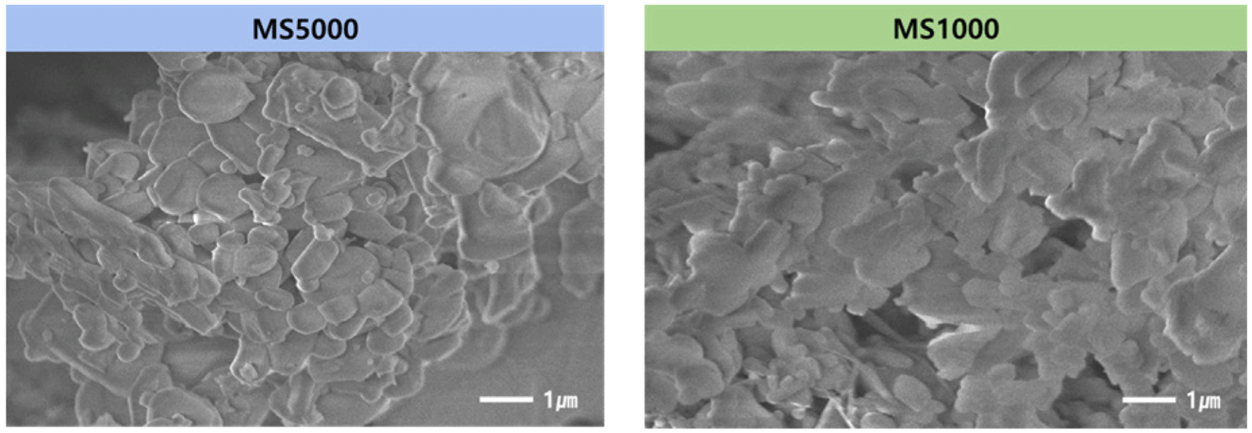
The silica particles were selected because they have an excellent thermal stability and electrical insulation properties, which help high-speed communication equipment operate reliably even in harsh environments. In addition, some research is being conducted to develop silica particles with low dielectric constant and apply them to PCBs for high-speed communications. The average particle sizes of each silica, measured using a laser scattering particle size distribution analyzer, were 1.862 ± 0.8648 μm and 5.898 ± 0.9879 μm for MS1000 and MS5000, respectively.37 SEM was used to observe the shape of the silica filler particles (Figure 2). We compared the SEM images of MS5000 and MS1000 and found that MS5000 had larger particles than MS1000. The silica particle sizes were highly non-uniform, as measured by a laser scattering particle size distribution analyzer. Both samples exhibited a wide range of particle sizes, indicating a large standard deviation. Most particles were spherical, but the MS5000 particles appeared more rounded and aggregated than the MS1000 particles.
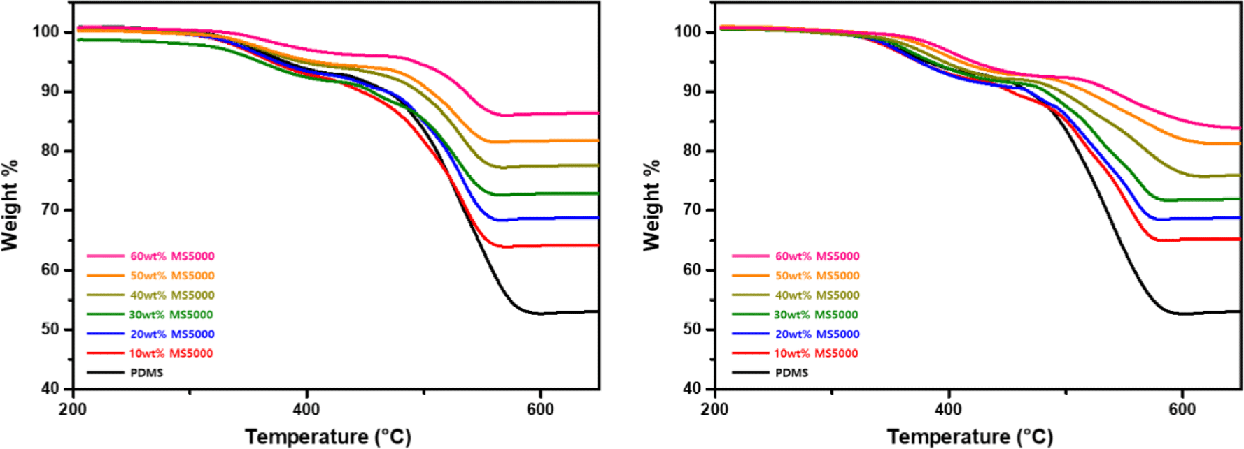
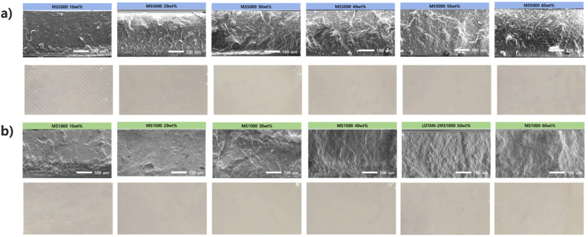
The silica particles were mixed with the PDMS prepolymer at a concentration of 10 to 60 wt% to produce low-dielectric polymer composite films. The cross-section of the PDMS– silica films exhibited no pores or foreign contaminants on the surface as shown in SEM, confirming that the silica fillers were evenly distributed within the PDMS matrix (Figure 3). To test the thermal stability of the PDMS–silica films, samples were heated up to 700°C, burning both the PDMS and PDMS–silica composites. The decomposition of all samples was estimated from the temperature when the weight loss was 10 wt%. The decomposition temperature of PDMS was 469°C. For films containing 10, 20, and 30 wt% of MS5000 silica filler, the decomposition temperatures were 447, 469, and 466 °C, respectively. For films with 40, 50, and 60 wt% of MS5000 filler, the decomposition temperatures increased to 495, 506, and 535°C (Figure 4). Similarly, for MS1000 filler, the decomposition temperatures for composite films with 10, 20, and 30 wt% filler were 453, 468, and 483°C, respectively. For films with 40, 50, and 60 wt% filler, they increased to 496, 518, and 540°C. The weight loss of PDMS was approximately 49.85 wt% at above 600°C, while the film with 60 wt% MS5000 filler had the highest thermal stability and only approximately 13 wt% weight loss. The weight loss of the film with 60 wt% MS1000 filler was also approximately 16 wt%. The superior thermal stability of silica compared with that of the PDMS polymer accounts for the increase in the heat resistance of the films with increasing silica filler content.
TGA was also used to analyze the actual silica content in the PDMS–silica composite. 49.85 wt% of the PDMS resin burned off, leaving 50.15 wt% residue. The actual silica content of the samples was calculated using the following equation (Eq. 1)38:
The actual silica content in the sample was 12–18 wt% higher than the amount initially added (Table 1). We speculate that PDMS could be lost during the spreading of the film owing to the nature of the blade coating process. Additionally, variations in the silica content between the MS5000 and MS1000 samples could arise from the interaction between the PDMS and silica particles, with this interaction potentially being influenced by differences in particle size. The dielectric properties were compared based on the actual silica content determined by TGA. The dielectric constant and dielectric loss of each PDMS–silica film were measured and correlated with the calculated actual silica content (Figure 5). The x-axis represents the actual silica content, and the y-axis represents the dielectric constant and dielectric loss values. Pure PDMS had a dielectric constant of 2.785 and a dielectric loss of 0.02255.
| MS5000 | Calculated weight % | MS1000 | Calculated weight % |
|---|---|---|---|
| 10wt% | 28.36 | 10wt% | 31.73 |
| 20wt% | 37.25 | 20wt% | 37.35 |
| 30wt% | 45.66 | 30wt% | 43.71 |
| 40wt% | 54.83 | 40wt% | 51.85 |
| 50wt% | 63.28 | 50wt% | 62.77 |
| 60wt% | 72.29 | 60wt% | 67.5 |
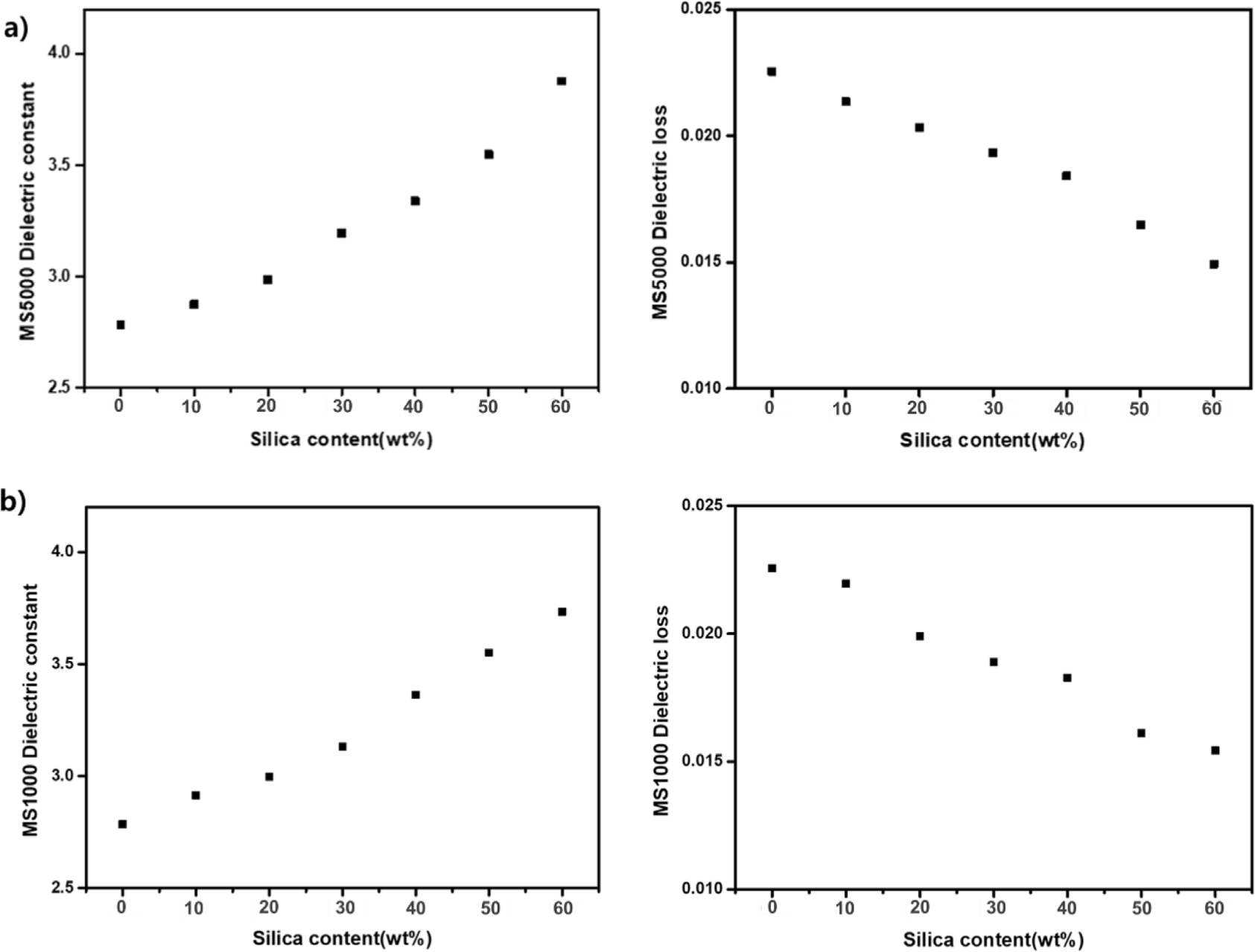
For the PDMS–silica films with the MS5000 filler, the dielectric constant increased with increasing MS5000 content, from 2.876 to 3.8782 as the filler content increased from 10 to 60 wt%. The dielectric loss decreased accordingly, from 0.0219 to 0.0154. Similarly, for the PDMS–silica films with the MS1000 filler, the dielectric constant increased with increasing MS1000 content, from 2.9135 to 3.7341. The dielectric loss decreased from 0.0213 to 0.0149. At 10 wt% filler content, the dielectric constants (Dk) for MS5000 and MS1000 were 2.9135 and 2.8760, respectively, whereas at 60 wt% filler content, they were 3.8781 and 3.734, respectively. The dielectric loss (Df) was 0.02136 for MS5000 and 0.2195 for MS1000 at 10 wt% filler content and 0.0154 for MS5000 and 0.0149 for MS1000 at 60 wt% filler content. The increased dielectric constant of the PDMS–silica film with the addition of more fillers is due to the higher dielectric constant of the MS5000 silica filler compared to PDMS.39 Meanwhile, the lower dielectric loss of the silica filler compared to PDMS results in a decrease in the dielectric loss of the PDMS–silica film as the filler content increases. The MS1000 composite showed similar results.
Controlling the filler content of resin–silica composites could yield optimal dielectric properties for applications operating at high frequencies above 10 GHz, where dielectric materials with extremely low dielectric loss are required.
The elongation and Young’s modulus of the PDMS–silica films were measured using a universal testing machine (UTM). To visually assess the flexibility and elasticity of the PDMS–silica films, weights (500 g) were used, and the films were folded in half for observation (Figure 6a). As the MS5000 silica content increased, the elongation of the films decreased from 78.031 to 41.864, 32.665, 30.265, 27.0265, and 17.790%, while the Young’s modulus increased from 389.84 to 1813.5, 3694, 6986.6, 9233.9, and 10896 MPa. For the films with increasing MS1000 silica content, the elongation decreased from 79.799 to 45.264, 39.906, 37.647, 34.18, and 27.704%, while the Young’s modulus increased from 279.7 to 4516.6, 7600.4, 7841.02, 8280.5, and 10375 MPa. The typical elongation of PDMS ranges from 100% to 900%, and its Young’s modulus is 1.2 ± 0.2 MPa. The film with 10 wt% filler content exhibited an elongation of 78.915% and Young’s modulus of 334.77 MPa and showed reduced elongation compared to standard PDMS values. The increase in the Young’s modulus with increasing filler content was due to the stiffness provided by the silica filler within the PDMS matrix, which enhanced the resistance to external loads. Conversely, the elongation decreased because the silica filler hindered the deformation of the PDMS chains. This phenomenon can be explained using the rule of mixtures (Eq. 2) and the Halpin-Tasi equation (Eq. 3), which describe the relationship between filler content, Young’s modulus, and elongation.40,41
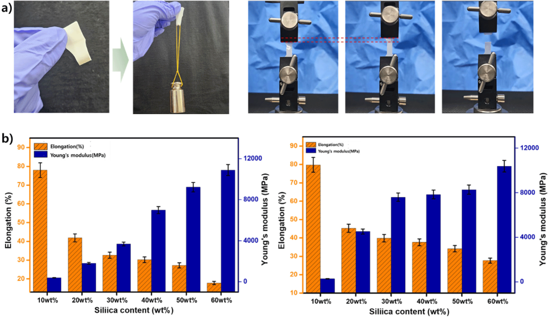
where E is the elastic modulus, Vf is the Silicon filler volume fraction, and η is the relationship parameter between the particles, matrix, and shape factor. The subscript f represents the reinforcing phase and m represents the matrix. The same trends were observed for the MS1000 PDMS– silica films, where the elongation decreased and Young’s modulus increased as the silica content increased. Although the elasticity was lower than that of pure PDMS, the films maintained flexibility at low filler contents. Balancing mechanical flexibility and signal loss is critical for high-speed communications. Our results show that low filler content (e.g., 10 wt%) provides higher flexibility but higher dielectric loss due to reduced filler interaction within the matrix, leading to higher polarization losses. Conversely, high filler content (e.g., 60 wt%) reduces flexibility as the rigid filler network hinders PDMS chain movement but improves dielectric performance due to the lower dielectric loss of silica. Therefore, an intermediate filler contents of 30–40 wt% are suitable for practical applications as they minimize this trade-off to achieve low signal loss while maintaining sufficient mechanical flexibility.
Conclusions
This study aims to develop new materials with low dielectric losses that are suitable for high-speed communication systems, particularly 5G networks. Composite films were fabricated using PDMS and silica fillers, and their dielectric properties and mechanical characteristics were evaluated. We also analyzed the particle sizes of MS5000 and MS1000 and investigated how the silica filler content affected the dielectric constant, dielectric loss, and mechanical properties of the films, including the thermal stability, elongation, and Young’s modulus. The experimental results showed that as the silica content increased, the dielectric constant of the films increased, whereas the dielectric loss, which affects the performance at high frequencies, decreased. The thermal stability improved with increasing silica filler content and the stiffness (Young’s modulus) of the films increased, whereas their elongation decreased. Based on these findings, adjusting the ratio of the silica filler can play a key role in minimizing signal degradation and ensuring high-speed signal transmission in applications requiring high-frequency performance, such as 5G+ communication systems. By developing films with low dielectric loss at frequencies above 10 GHz, this study demonstrates the potential of these materials for high-frequency applications such as PCBs for 5G communications.


