Elastomers and Composites
The Rubber Society of Korea
Article

Influence of Slip Angle on Abrasion Behavior of NR/BR Vulcanizates

Eunji Chae*, Sung-Seen Choi*,
*Department of Chemistry, Sejong University, 209 Neungdong-ro, Gwangjin-gu, Seoul 05006, Republic of Korea
Corresponding author E-mail: sschoi@sejong.ac.kr

© Copyright 2023 The Rubber Society of Korea. This is an Open-Access article distributed under the terms of the Creative Commons Attribution Non-Commercial License (http://creativecommons.org/licenses/by-nc/4.0/) which permits unrestricted non-commercial use, distribution, and reproduction in any medium, provided the original work is properly cited.

Received: Jan 25, 2023; Revised: Feb 03, 2023; Accepted: Feb 11, 2023

Published Online: Mar 31, 2023

Abstract

Abrasion tests of model tire tread compounds (NR and NR/BR blend compounds) were performed at different slip angles (1° and 7°) using a laboratory abrasion tester. The abrasion behavior was investigated by analyzing the worn surface and wear particles. The abrasion spacing formed on the specimen worn at the large slip angle of 7° was significantly narrower than that at the small slip angle of 1°, while the abrasion depth for the specimen worn at 7° was lower than that at 1°. The abrasion spacing and depth tended to be narrower and lower, respectively, as the BR content increased. The abrasion patterns were clearly visible on the outside of the specimen for the slip angle of 1° but not for 7°. The wear particles had a rough surface and there were numerous micro-bumps. It was found that the crosslink density affected the abrasion patterns and morphologies of the wear particles.

Keywords: abrasion pattern; slip angle; wear particle; morphology; rubber vulcanizate

Introduction

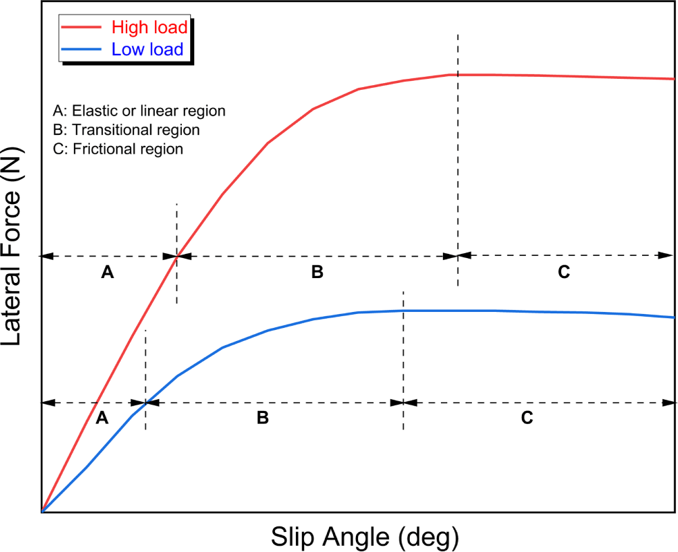
When a vehicle corners, the tire generates lateral force to support the vehicle.1,2 Lateral force is the force transmitted by a tire to the ground in the vertical direction to the plane of symmetry of the tire. Slip angle (or sideslip angle) is the angle between the center plane of the wheel subjected to lateral force.1,3-5 General relationship between slip angle and lateral force is described in Figure 1, which its curve can be divided into three regions; elastic or linear, transitional, and frictional parts.1,2,6-11 In the elastic region where the slip angle is small, the lateral force linearly increases with the slip angle and the slope is called the cornering stiffness. In the transitional region, the portion of the tire contact patch reduces and the lateral force increases less as the slip angle increases. The peak point between the transitional and frictional regions usually appears around 5°, and it increases with increase in the load. Frictional curves have specific characteristics depending on the rubber compound and tread pattern of a tire.11
ec-58-1-17-g1
Figure 1. General relationship between slip angle and lateral force of a tire.
Download Original Figure

When a rubber vulcanizate is worn, periodic parallel ridge patterns are formed on the surface.12-18 The first step in ridge generation is the formation of small particles by micro-tears.12 The size and shape of the wear particles depend on the frictional force. When the load is high, the abrasion spacing tends to widen, and at a low load, stripes with narrow intervals are observed.19 Abrasion depth can be used to estimate the amount of material removed as the wear particles.14,20 Since partial wear occurs on the tire surface due to the slip angle, the abrasion depth in the slip direction is greater than that in the other direction.20 A laboratory abrasion tester has been used for abrasion test of tire tread compounds by applying various driving conditions.21-23

Abrasion of tire treads acts as a source of contamination from the non-exhaust of vehicles. Tire wear particles (TWPs) are one of the main components of microplastics.24,25 TWPs can flow into rivers, lakes, and seas to be deposited in the sediment.26 When TWP breaks into fine particles, it becomes a source of air pollution as fine dust in the air.27,28

Natural rubber (NR) and butadiene rubber (BR) are generally used for manufacturing tire tread compounds.29-32 In this study, model tire tread compounds (NR and NR/BR blends) were prepared and abrasion test was performed using a laboratory abrasion tester. Two slip angles of 1° and 7° were employed, which correspond to the elastic and frictional regions as shown in Figure 1. The abrasion behavior was investigated by analysis of the worn surface of abrasion specimen and the wear particles.

Experimental

Three model rubber compounds were prepared using NR (TSR20) and BR (BR01 of Korea Kumho Petroleum Co., Republic of Korea). Formulations of the three rubber compounds were same except for the rubber composition. The sample codes were N10B0, N8B2, and N6B4 for the NR = 100, NR/BR = 80/20, and NR/BR = 60/40 compounds, respectively. Mixing was performed in a Banbury type mixer, and the initial temperatures of the mixer were 110 and 80°C for master batch (MB) and final mixing (FM) stages, respectively. The abrasion specimens were prepared by curing the rubber compound at 160°C for the maximum cure time (tmax) in a compression mold (83 mm diameter and 19 mm thickness).

Abrasion test was performed using LAT100 tire tread compound tester of VMI group (the Netherlands). Electro Corundum Disc Grain 60 of VMI group (the Netherlands) was used as the abrasive disk. The load force was 75 N and the velocity was 25 km/h. Two slip angles 1° and 7° were applied. The abrasion tests were performed for 3 and 0.5 h for the slip angles of 1° and 7°, respectively. Surface morphologies of the abrasion specimens were observed using an image analyzer (EGVM 35B, EG Tech. Co., Republic of Korea). Morphologies of the wear particles were observed using a scanning electron microscope (CUBE-II tabletop SEM, Emcrafts Co., Republic of Korea).

Crosslink densities of the samples were measured by the swelling method.33-35 Organic additives in the sample were removed by extracting with THF and n-hexane for 3 and 2 days, respectively, and the sample was dried for 2 days at room temperature. The weight of the organic materials-extracted sample was measured. The organic materials-extracted sample was soaked in toluene for 2 days at room temperature and the weights of the swollen samples were measured. The crosslink densities (Xcs) were calculated using the Flory–Rehner equation.35

Results and Discussion

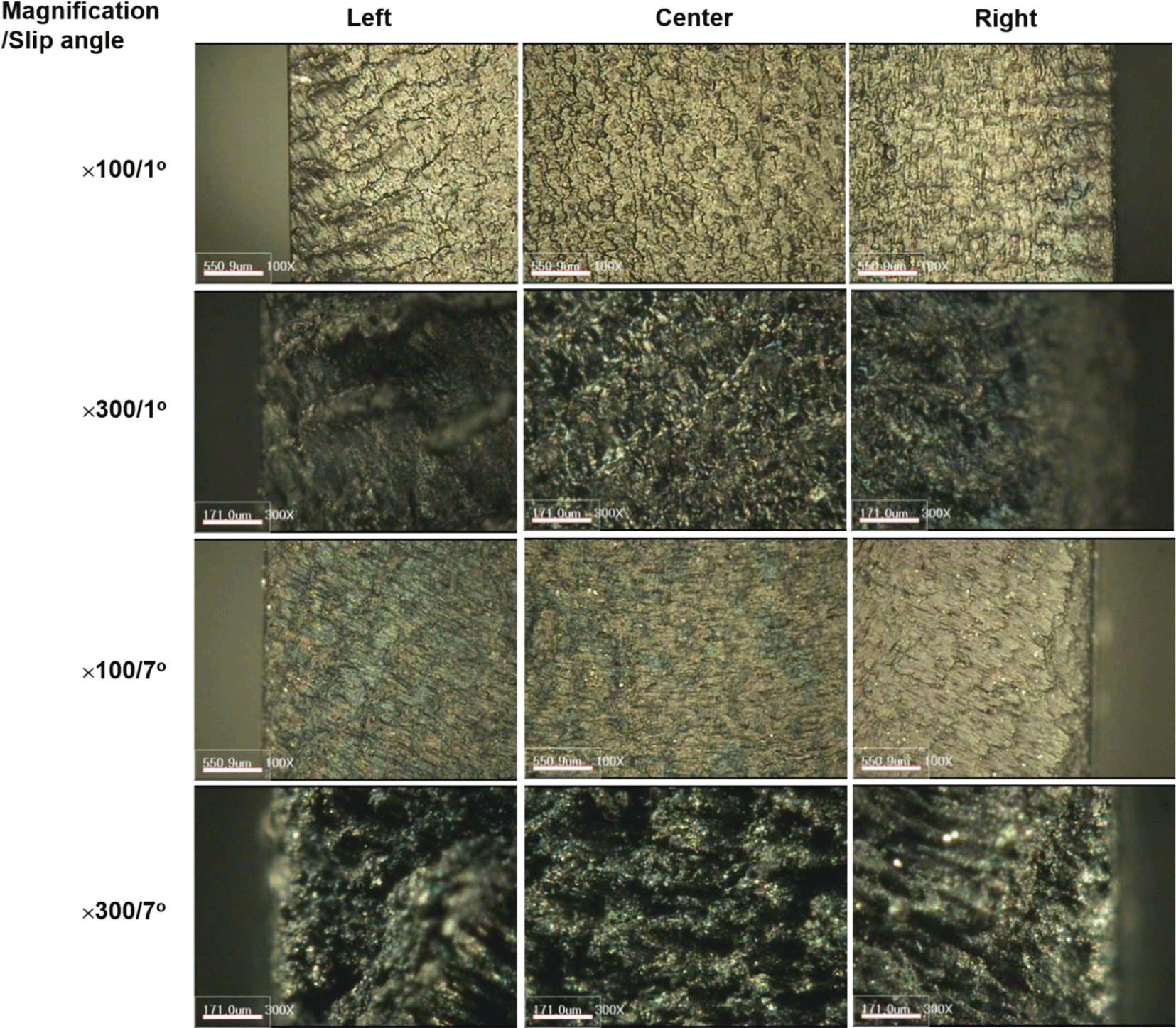
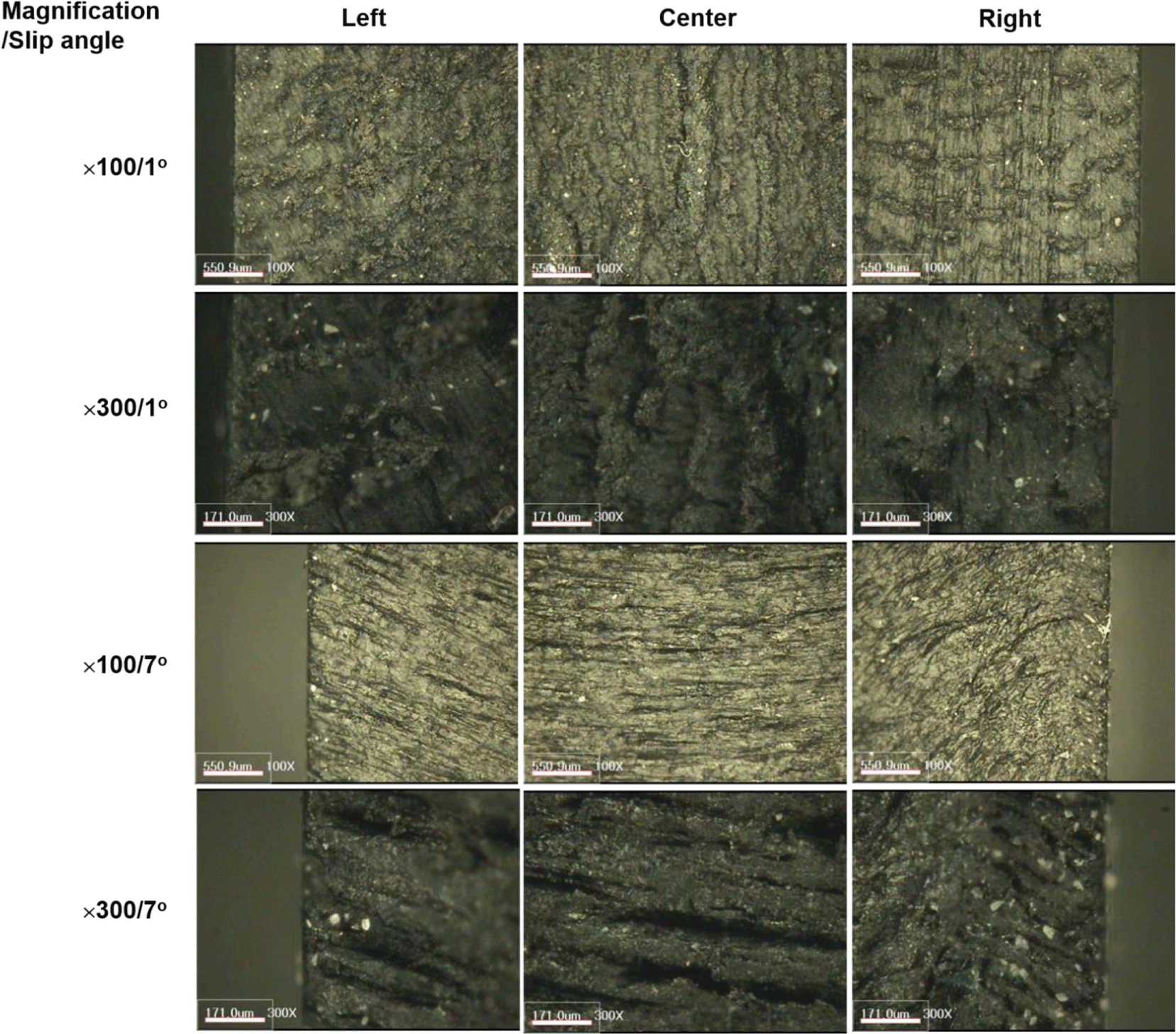
Worn surfaces of the abrasion specimens after the abrasion tests were observed by dividing into three parts of the left, center, and right. Figure 2 shows magnified images of the worn surfaces of the N10B0 sample after the abrasion test. The images clearly show the abrasion patterns of spacing and depth. In the 300 time-magnified image at the slip angle of 1°, a large hole was observed. The worn surface looks like sticky or wet. The abrasion spacing notably became narrower as the slip angle increased. The narrower spacing denotes that smaller wear particles were produced. In general, size distribution of the wear particles produced at higher slip angle shifts to smaller size than that of the wear particles produced at lower one.22
ec-58-1-17-g2
Figure 2. Magnified images of the worn surfaces of the N10B0 abrasion specimen after the abrasion test.
Download Original Figure

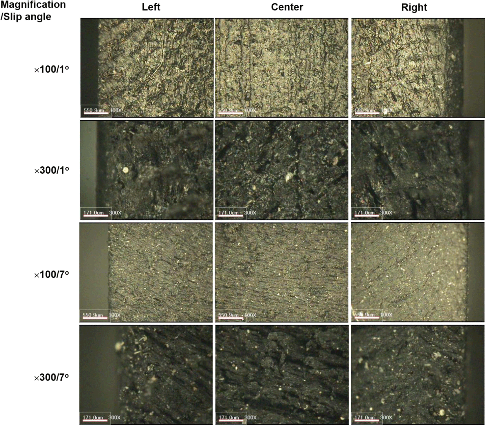
Figure 3 shows magnified images of the worn surfaces of the N8B2 sample after the abrasion test. The worn surface looks like dry unlike the N10B0 sample. Some small particle on the worn surface were observed. They should be wear particles generated from the abrasive. The abrasion spacing notably became narrower as the slip angle increased and the abrasion depth became lower. The narrower spacing and lower depth implies that smaller wear particles were produced. Figure 4 shows magnified images of the worn surfaces of the N6B4 sample after the abrasion test. The worn specimen has dry surface like the N8B2 sample. Some deeply-dug holes could be observed in the 300 time-magnified images. The abrasion spacing notably became narrower as the slip angle increased and the abrasion depth became lower. The narrower spacing and lower depth implies that smaller wear particles were produced.
ec-58-1-17-g3
Figure 3. Magnified images of the worn surfaces of the N8B2 abrasion specimen after the abrasion test.
Download Original Figure
ec-58-1-17-g4
Figure 4. Magnified images of the worn surfaces of the N6B4 abrasion specimen after the abrasion test.
Download Original Figure

The abrasion spacing tended to be narrower and the abrasion depth tended to be lower as the BR content increased. Hence, it can be concluded that size distribution of the wear particles produced from NR/BR blend compounds will shift to smaller size as the BR portion in the compound increases. The experimental results can be explained by the crosslink density. Crosslink densities of the N10B0, N8B2, and N6B4 samples were 1.8×10⁻⁴, 2.1×10⁻⁴, and 2.4×10⁻⁴ mol/cm3, respectively. By increasing the BR content, the crosslink density increased.

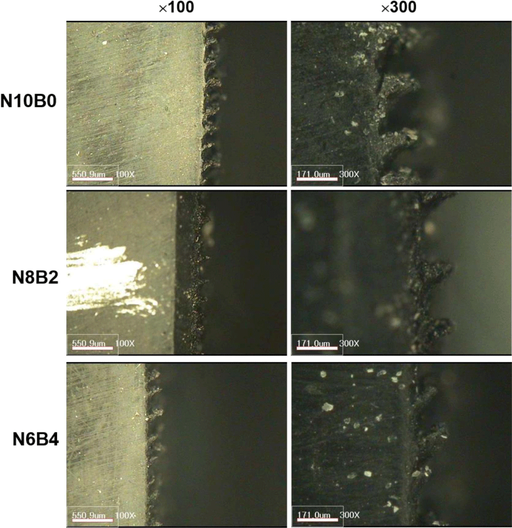
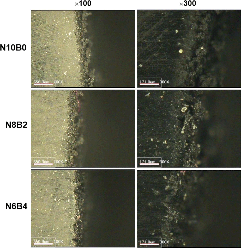
Side-views of the abrasion specimens after the abrasion test were observed to examine the abrasion patterns formed on the outside part. Figures 5 and 6 show the magnified side-views of the abrasion specimens after the abrasion tests at the slip angles of 1° and 7°, respectively. For the samples tested at the slip angle of 1°, bumps were clearly observed and the abrasion patterns could be examined from the images. Size of the bumps reduced as the BR content increased. Heights of the bumps were less than 200μm and they tended to decrease as the BR content increased. For the samples tested at the slip angle of 7°, the abrasion patterns could not be observed and the surface was squashed. By increasing the BR content, the worn surface became less rough.
ec-58-1-17-g5
Figure 5. Magnified side-view images of the worn abrasion specimens. The slip angle is 1°.
Download Original Figure
ec-58-1-17-g6
Figure 6. Magnified side-view images of the worn abrasion specimens. The slip angle is 7°.
Download Original Figure

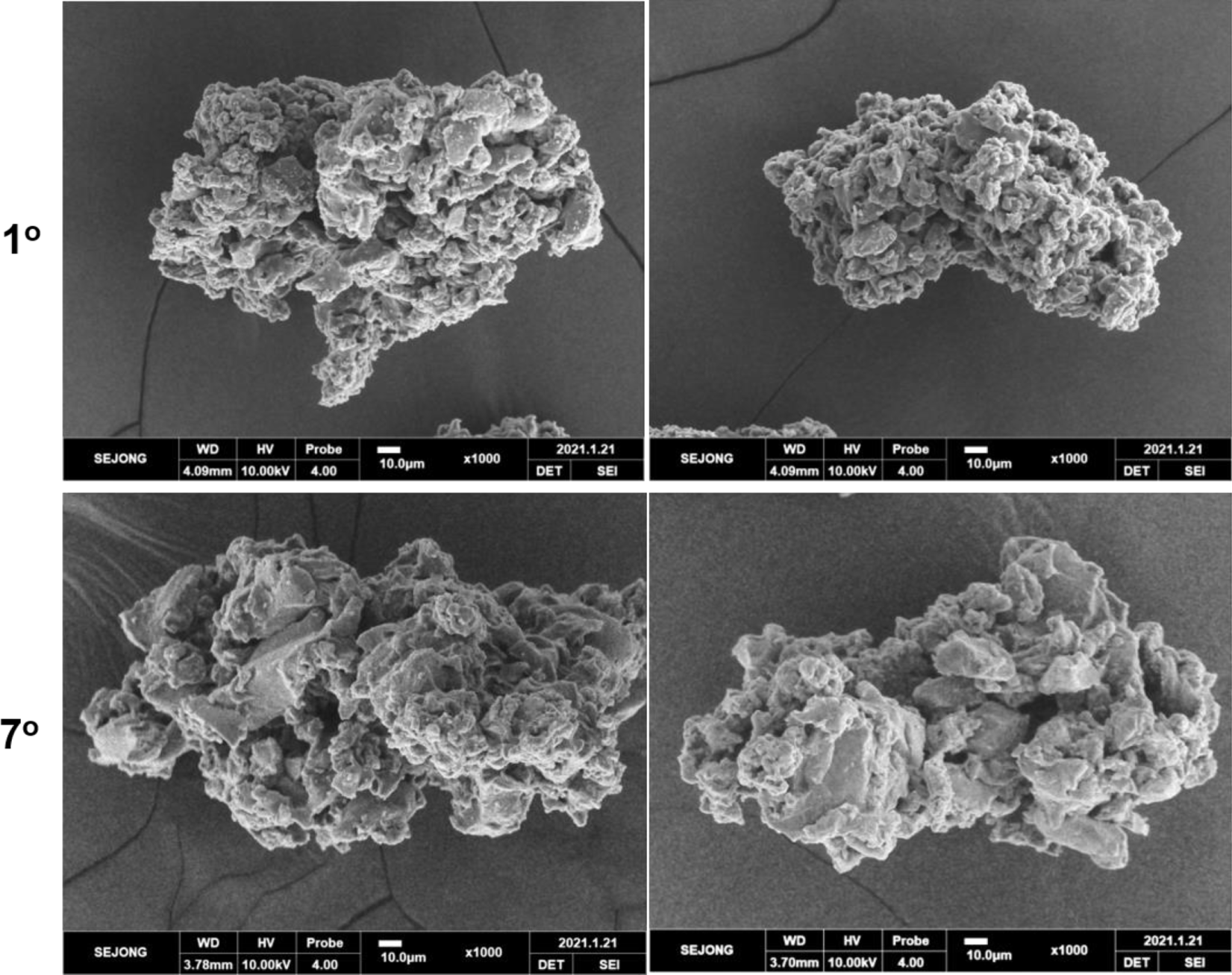
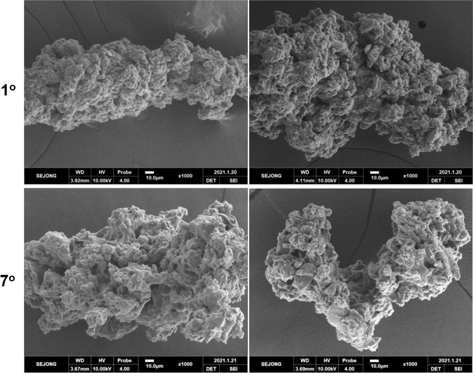
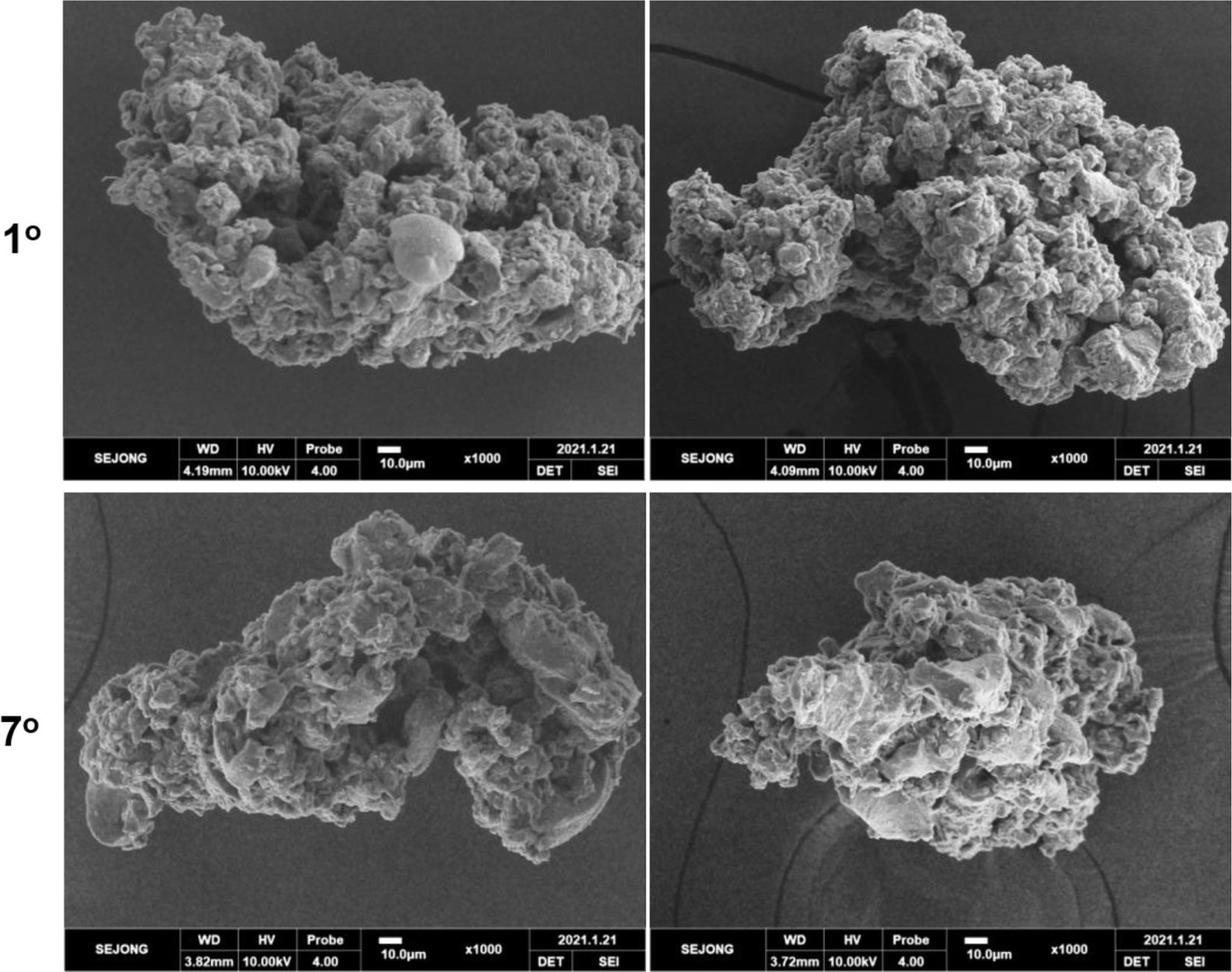
Figures 7, 8, and 9 show SEM images of the wear particles of 106-212 μm produced from the N10B0, N8B2, and N6B4 samples. From the SEM images, morphologies of the wear particles could be observed in detail. The surfaces are very rough and have a lot of micro-bumps. Sizes of the micro-bumps about 10μm or less. The micro-bump size can be changed depending on the wear particle size. Formation of the micro-bumps may be due to the various micro-regions in the sample. A sulfur-cured rubber sample reinforced with carbon black has various microstructures influenced by carbon black and sulfur crosslinks. Micro-regions including carbon black can have different properties from those without carbon black, which should lead to different abrasion behavior. Properties of micro-regions with high and low crosslink densities are different from each other, and the properties are also dependent on crosslink types. Sulfur vulcanization makes varying crosslink types like mono-, di-, and polysulfides.36-38 Crosslink type and density of a rubber vulcanizate determine the physical properties such as modulus, hardness, resilience, elongation at break, heat build-up, and so forth.38-41 By increasing crosslink density, modulus and abrasion resistance increase, while tensile strength increase in proportion to the di- and polysulfide content. Physical properties of rubber vulcanizates affect the abrasion behavior.42-45 High modulus at high strain, elongation at break, and tensile strength can reduce abrasion rate of a rubber vulcanizate.
ec-58-1-17-g7
Figure 7. SEM images (×1000) of the wear particles of 106-212 μm produced from the N10B0 abrasion specimen. The slip angles are marked.
Download Original Figure
ec-58-1-17-g8
Figure 8. SEM images (×1000) of the wear particles of 106-212 μm produced from the N8B2 abrasion specimen. The slip angles are marked.
Download Original Figure
ec-58-1-17-g9
Figure 9. SEM images (×1000) of the wear particles of 106-212 μm produced from the N6B4 abrasion specimen. The slip angles are marked.
Download Original Figure

Surface of the wear particle tended to be rougher and shapes of the micro-bumps tended to be more clear as the BR content increased. There were some micro-potholes in the were particles, and level of the micro-potholes tended to increase as the BR content increased. Difference in the morphologies depending on the BR content can be explained by increasing heterogeneity of the micro-regions due to differences in the crosslinks and rubber compositions. Crosslink types and densities between NR and BR compounds should be different if the compound formulations are same except for the rubber composition. This difference may lead to different micro-regions. It was reported that rubber compositions of the wear particles produced from an NR/BR blend sample was different from each other.45

Conclusions

Worn surface of the N10B0 sample was sticky, whereas those of the N8B2 and N6B4 samples were dry. The abrasion spacing notably became narrower and the abrasion depth became lower as the slip angle increased. The narrower spacing and lower depth implies that smaller wear particles were more produced. Size of the bumps formed on the worn surface at the slip angle of 1° reduced as the BR content increased. Heights of the bumps were less than 200μm and they tended to decrease as the BR content increased. However, for the samples tested at the slip angle of 7°, the abrasion patterns could not be observed in the side-view images. A lot of micro-bumps were observed on the wear particle surface. On the whole, wear particles produced from the abrasion test at the slip angle of 7° show rougher surfaces than those generated at the slip angle of 1°. Various and rough shapes of the wear particles mean that abrasion processes are very complex. The abrasion patterns were related to the morphologies and size distributions of the wear particles. Crosslink density affected the abrasion patterns and morphologies of the wear particles.

Acknowledgements

This work was supported by the Technology Innovation Program funded by the Ministry of Trade, Industry and Energy, Republic of Korea (Project Number 20010851).

Notes

Conflict of Interest : The authors declare that there is no conflict of interest.

Publisher’s Note The Rubber Society of Korea remains neutral with regard to jurisdictional claims in published articles and institutional affiliations.

References

1.

M. Salehi, J. W. M. Noordermeer, L. A. E. M. Reuvekamp, W. K. Dierkes, and A. Blume, “Measuring rubber friction using a Laboratory Abrasion Tester (LAT100) to predict car tire dry ABS braking”, Tribol. Int., 131, 191 (2019).

2.

S.-L. Koo, H.-S. Tan, and M. Tomizuka, “Nonlinear tire lateral force versus slip angle curve identification”, Proceedings of the 2004 American Control Conference, Boston, 2128 (2004).

3.

A. Todorut and N. Cordos, “Evaluation of the vehicle sideslip angle according to different road conditions”, ed. by N. Burnete and B. O. Varga, p.814, Springer, 2019.

4.

M. Heinz, “An universal method to predict wet traction behaviour of tire tread compounds on the laboratory”, J. Rubber Res., 13, 91 (2010).

5.

A. Doria, M. Tognazzo, G. Cusimano, V. Bulsink, A. Cooke, and B. Koopman, “Identification of the mechanical properties of bicycle tyres for modelling of bicycle dynamics”, Veh. Syst. Dyn., 51, 405 (2013).

6.

N. Rao, “An approach to rollover stability in vehicles using suspension relative position sensors and lateral acceleration sensors”, Texas A&M University master thesis, 2005.

7.

W. F. Milliken and D. L. Milliken, “Race Car Vehicle Dynamics”, SAE International, 1995.

8.

K. Nam, “Application of novel lateral tire force sensors to vehicle parameter estimation of electric vehicles”, Sensors, 15, 28385 (2015).

9.

E. M. Kasprzak, K. E. Lewis, and D. L. Milliken, “Tire Asymmetries and Pressure Variations in the Radt/Milliken Nondimensional Tire Model”, Proceeding of the SAE Automotive Dynamics, Stability and Controls Conference and Exhibition, USA., 1 (2006).

10.

J. Kim, “Estimation of tire forces using vehicle linear accelerations and yaw rate”, Trans. Korean Soc. Automot. Eng., 27, 747 (2019).

11.

M. Salehi, J. W. M. Noordermeer, L. A. E. M. Reuvekamp, T. Tolpekina, and A. Blume, “A new horizon for evaluating tire grip within a laboratory environment”, Tribol. Lett., 68, 37 (2020).

12.

A. K. Bhowmick, “Ridge formation during the abrasion of elastomers”, Rubber Chem. Technol., 55, 1055 (1982).

13.

A. Schallamach, “Friction and abrasion of rubber”, Wear, 1, 384 (1958).

14.

A. Zmitrowicz, “Wear patterns and laws of wear – a review”, J. Theor. Appl. Mech., 44, 219 (2006).

15.

B. Setiyana, R. Ismail, J. Jamari, and D. J. Schipper, “An analytical study of the wear pattern of an abraded rubber surface: the interaction model”, Tribol.-Mater. Surf. Interfaces, 12, 186 (2018).

16.

Y. Fukahori and H. Yamazaki, “Mechanism of rubber abrasion, Part I: abrasion pattern formation in natural rubber vulcanizate”, Wear, 171, 195 (1994).

17.

Y. Fukahori and H. Yamazaki, “Mechanism of rubber abrasion Part 2. general rule in abrasion pattern formation in rubber-like materials”, Wear, 178, 109 (1994).

18.

K. A. Grosch, “Rubber abrasion and tire wear”, Rubber Chem. Technol., 81, 470 (2008).

19.

Y. Uchiyama and Y. Ishino, “Pattern abrasion mechanism of rubber”, Wear, 158, 141(1992).

20.

G. Tong and X. Jin, “Study on the simulation of radial tire wear characteristics”, WSEAS Trans. Syst., 11, 419 (2012).

21.

S.-S. Choi, S. R. Yang, E. Chae, and C. E. Son, “Influence of carbon black contents and rubber compositions on formation of wear debris of rubber vulcanizates”, Elast. Compos., 55, 108 (2020).

22.

C. E. Son, S. R. Yang, and S.-S. Choi, “Abrasion behaviors of NR/BR compounds using laboratory abrasion tester”, Elast. Compos., 56, 12 (2021).

23.

E. Chae, S. R. Yang, and S.-S. Choi, “Test method for abrasion behavior of tire tread compounds using the wear particles”, Polym. Test, 115, 107758 (2022).

24.

I. Järlskog, A.-M. Strömvall, K. Magnusson, M. Gustafsson, M. Polukarova, H. Galfi, M. Aronsson, and Y. Andersson-Sköld, “Occurrence of tire and bitumen wear microplastics on urban streets and in sweepsand and washwater”, Sci. Total Environ., 729, 138950 (2020).

25.

M. L. Kreider, J. M. Panko, B. L. McAtee, L. I. Sweet, and B. L. Finley, “Physical and chemical characterization of tire related particles: Comparison of particles generated using different methodologies”, Sci. Total Environ., 408, 652 (2010).

26.

P. J. Kole, A. J. Löhr, F. G. A. J. V. Belleghem, and A. M. J. Ragas, “Wear and tear of tyres: A stealthy source of microplastics in the environment”, Int. J. Environ. Res. Public Health, 14, 1265 (2017).

27.

A. Wik and G. Dave, “Occurrence and effects of tire wear particles in the environment – A critical review and an initial risk assessment”, Environ. Pollut., 157, 1 (2009).

28.

F. Amato, F. R. Cassee, H. D. V. D. Gon, R. Gehrig, M. Gustafsson, W. Hafner, R. M. Harrison, M. Jozwicka, F. J. Kelly, T. Moreno, A. S. H. Prevot, M. Schaap, J. Sunyer, and X. Querol, “Urban air quality: The challenge of traffic non-exhaust emissions”, J. Hazard. Mater., 275, 31 (2014).

29.

C. Sirisinha, P. Sae-oui, K. Suchiva, and P. Thaptong, “Properties of tire tread compounds based on functionalized styrene butadiene rubber and functionalized natural rubber”, J. Appl. Polym. Sci., 137, 48696 (2020).

30.

M. H. R. Ghoreishy, M. Alimardani, R. Z. Mehrabian, and S. T. Gangali, “Modeling the hyperviscoelastic behavior of a tire tread compound reinforced by silica and carbon black”, J. Appl. Polym. Sci., 128, 1725 (2013).

31.

T. Miyazaki, “Rubber Composition”, European patent EP3459996 (2017).

32.

S. Schaal, M. Martin, and L. Migliarini, “Tyre having a high wear resistance, tread band and elastomeric composition used therein”, U.S. patent 2005O234165 (2005).

33.

S.-S. Choi and J.-C. Kim, “Lifetime prediction and thermal aging behaviors of SBR and NBR composites using crosslink density changes”, J. Ind. Eng. Chem., 18, 1166 (2012).

34.

S.-S. Choi and D.-H. Han, “Strain effect on recovery behaviors from circular deformation of natural rubber vulcanizate”, J. Appl. Polym. Sci., 114, 935 (2009).

35.

P. J. Flory, “Statistical mechanics of swelling of network structures”, J. Chem. Phys., 18, 108 (1950).

36.

S.-S. Choi and E. Kim, “A novel system for measurement of types and densities of sulfur crosslinks of a filled rubber vulcanizate”, Polym. Test., 42, 62 (2015).

37.

W. Salgueiro, A. Marzocca, A. Somoza, G. Consolati, S. Cerveny, F. Quasso, and S. Goyanes, “Dependence of the network structure of cured styrene butadiene rubber on the sulphur content”, Polymer, 45, 6037 (2004).

38.

S.-S. Choi, I.-S. Kim, and C.-S. Woo, “Influence of TESPT content on crosslink types and rheological behaviors of natural rubber compounds reinforced with silica”, J. Appl. Polym. Sci., 106, 2753 (2007).

39.

A. Y. Coran, “Vulcanization: conventional and dynamic”, Rubber Chem. Technol., 68, 351 (1995).

40.

A. Mousa and J. Karger-Kocsis, “Rheological and thermodynamical behavior of styrene/butadiene rubber-organoclay nanocomposites”, Macromol. Mater. Eng., 286, 260 (2001).

41.

M. Jacob, S. Thomas, and K. T. Varughese, “Mechanical properties of sisal/oil palm hybrid fiber reinforced natural rubber composites”, Compos. Sci. Technol., 64, 955 (2004).

42.

A. H. Muhr and A. D. Roberts, “Rubber abrasion and wear”, Wear, 158, 213 (1992).

43.

J. K. Oleiwi, M. S. Hamza, and M. Sh. Abed, “Improving the properties of the tire tread by adding SiO2 and Al2O3 to SBR rubber”, Int. J. Appl. Eng. Res., 5, 1637 (2010).

44.

C. Sirisinha, P. Sae-oui, K. Suchiva, and P. Thaptong, “Properties of tire tread compounds based on functionalized styrene butadiene rubber and functionalized natural rubber”, J. Appl. Polym. Sci., 137, 48696 (2020).

45.

N. Torbati-Fard, S. M. Hosseini, and M. Razzaghi-Kashani, “Effect of the silica-rubber interface on the mechanical, viscoelastic, and tribological behaviors of filled styrene-butadiene rubber vulcanizates”, Polym. J., 52, 1223 (2020).

46.

E. Chae and S.-S. Choi, “Influence of particle size on inhomogeneity in rubber compositions of NR/BR blend wear particles by single particle analysis”, Polym. Adv.Technol., 33, 897 (2022).