Introduction
Wear properties of tire tread rubber compounds are generally estimated using lab abrasion testers such as cut and chip (CC), Lambourn, DIN (Deutsches Institut für Normung), and LAT100 (Laboratory Abrasion Tester) abrasion testers.1-18 The CC abrasion tester is designed to evaluate the wear properties of rubber compounds under harsh conditions such as direct contact with rocks, gravel, and uneven road surface.1-7 The Lambourn abrasion test is performed using a small disc-shaped specimen and a large abrasive wheel, and talc powder is introduced between the specimen and abrasive to prevent smearing during the abrasion test.8-10 The DIN abrasion tester is one of the standardized tests used to characterize the abrasion resistance of rubber, and its test time is short.11-13 Using the laboratory abrasion tester (LAT100), abrasion test can be conducted by varying some parameters such as slip angle, load, speed, and temperature.14-18 Several researches compared the test results obtained by different abrasion testers, and the abrasion test results often show different trends depending on the abrasion testers.19-21
Abrasion behavior has been usually studied in terms of abrasion rate and pattern.22-25 The shapes and size distribution of tire tread wear particles are important for understanding the associated environmental pollution, and abrasion behavior of a tire tread rubber compound has been recently studied in terms of the wear particles.26 However, researches on the abrasion behavior based on the wear particles are still lacking. In this study, silica-filled styrene-butadiene rubber (SBR) compounds were prepared, and the abrasion behavior was investigated in terms of the shapes and size distribution of the wear particles. The abrasion tests were conducted using four common abrasion testers of CC, Lambourn, DIN, and LAT100 abrasion testers.
Silica-filled SBR compounds are used for tire treads of passenger cars.27-29 Hydrocarbon resins have been employed to improve unvulcanized and vulcanized rubber compounds.30-34 Dicyclopentadiene (DCPD) resin is a low molecular weight thermoplastic unsaturated hydrocarbon resin obtained by polymerization of monomers from C5 and C9 fractions.35-38 It offers good adhesive properties and is used as a tackifier in rubber products.39-42 In this study, influence of DCPD resin on abrasion behavior of a silica-filled rubber compound.
Experimental
Two silica-filled SBR compounds (SBR 1712 = 123.5 phr, silica = 80 phr, silane (X-50S) = 8 phr, other ingredients = 20 phr) were used for preparation of the abrasion specimens. Difference in the formulations between the two compounds was dicyclopentadiene (DCPD) resin of 20 phr. Sample codes of the two SBR compounds were named as SBR-0 and SBR-R for without and containing the DCPD resin. Four abrasion testers of cut and chip (CC), Lambourn, DIN, and LAT100 abrasion testers were employed. Cut and chip abrasion tester of CC-2020 (Myungji Tech Co., Republic of Korea) was used. Size of the specimen is 50 mm outer diameter, 13 mm inner diameter, and 13 mm thickness. Rotation speed of the sample was 750 rpm and the chipping speed was 60 rpm. Width of the chipping blade is 6 mm. Two specimens were tested for 10 min each. Lambourn abrasion tester of AB-1165 (Ueshima Seisakusho Co., Japan) was used. Dimension of the specimen was 49 mm outer diameter, 23 mm inner diameter, and 10 mm thickness. Speeds of the sample and abrasive wheel were 50 and 40 m/min, respectively, and the slip ratio was 19.7%. The load was 44.8 N and the chamber temperature was 35°C. The outer diameter of the abrasive wheel was 175 mm and the width was 25 mm. 80 grit sandpaper was attached to the abrasive wheel. Talc was introduced with the minimal injection level. Each specimen was tested for 10 min.
DIN abrasion tester of WL210A (Withlab Co., Republic of Korea) was used. Size of the abrasion specimen is 16 mm diameter and 8 mm thickness. Diameter of the drum surrounded by 60 grit sandpaper was 150 mm and the rotation speed was 40 rpm. When the test is started, the specimen is moved 40 m from right to left of the tester on the rotating abrasive drum. Two specimens were abraded for 3 min each. LAT100 tire tread compound tester (VMI group, the Netherlands) was used. Size of the abrasion specimen was 80 mm diameter and 19 mm thickness. Electro Corundum Disc Grain 60 of VMI group (the Netherlands) was used as the abrasive disk. The load force was 75 N and the slip angle was 3°. The abrasion test was conducted for 1 h and the velocity was 25 km/h.
The wear particles generated by each tester were collected and separated by size using a sieve shaker of an Octagon 200 (Endecotts Co. UK). The standard sieves of 1000, 500, 212, 106, 63, 38, and 20 μm were used. Shapes of the wear particles were observed using an image analyzer (EGVM35B, EG Tech Co., Republic of Korea). The physical properties were measured using a Universal Testing Machine (Instron 6021) at a cross-head speed of 200 mm/min.
Crosslink densities of the samples were measured by the swelling method.43-45 The sample was cut with dimension of 0.5×0.5 cm2 and its thickness was about 2 mm. Organic additives in the sample were removed by extracting with THF and n-hexane for 3 and 2 days, respectively, and the sample was dried for 2 days at room temperature. The weight of the organic materials-extracted sample was measured. The organic materials-extracted sample was soaked in toluene for 2 days at room temperature and the weights of the swollen samples were measured. The crosslink densities (Xcs) were calculated using the Flory-Rehner equation (1)46
where v2 is the volume fraction of the crosslinked polymer, χ is the interaction parameter between the polymer and solvent, V1 is the molar volume of the swelling solvent. The v2 is obtained by the equation (2)
where m1 and m2 are the solvent and specimen weights at equilibrium swelling, respectively, and ρ1 and ρ2 are the densities of swelling solvent and unswollen rubber sample, respectively. Interaction parameters of SBR with toluene are 0.446.47
Results and Discussion
Physical properties of the SBR-0 and SBR-R samples are summarized in Table 1. The SBR-0 sample showed higher moduli and tensile strength than the SBR-R sample, whereas the former had lower elongation at break than the latter. This was because the SBR-0 sample had higher crosslink density than the SBR-R sample: crosslink densities of the SBR-0 and SBR-R samples were 8.23×10⁻⁵ and 6.98×10⁻⁵ mol/cm3, respectively. The lower crosslink density of SBR-R sample may be due to preventing crosslinking reactions by the resin molecules.
The abrasion rates showed different trends depending on the type of abrasion testers (Table 2). For the DIN abrasion test, since the specimen got out of the sample holder during the test, the abrasion test could not be performed properly. The order of abrasion rate according to the abrasion tester was CC > Lambourn > LAT100. For the CC abrasion test, the abrasion rate of the SBR-0 sample was lower than that of the SBR-R sample. The abrasion test results using an LAT100 abrasion tester showed the same trend with the CC test. These results could be explained by the difference in the crosslink densities of the two samples. In general, abrasion rate of a rubber vulcanizate with high crosslink density is lower than that of a rubber vulcanizate with low crosslink density. The SBR-0 sample had higher crosslink density than the SBR-R sample. For the Lambourn abrasion test, the abrasion rate of SBR-0 sample was higher than that of the SBR-R sample. This was an interesting result because the SBR-0 sample had higher crosslink density than the SBR-R sample. The Lambourn abrasion test accelerates the abrasion rate by applying talc powder. For real driving conditions, a lot of mineral particles are present on the road. The improved abrasion rate of SBR-R sample may be due to slippage effect by adding the resin. The slippery surface can reduce the friction with the talc powder to lead decreasing abrasion rate.
| Compound | Abrasion tester | ||
|---|---|---|---|
| Cut and chip | Lambourn | LAT100 | |
| SBR-0 | 137 | 48 | 6 |
| SBR-R | 185 | 39 | 11 |
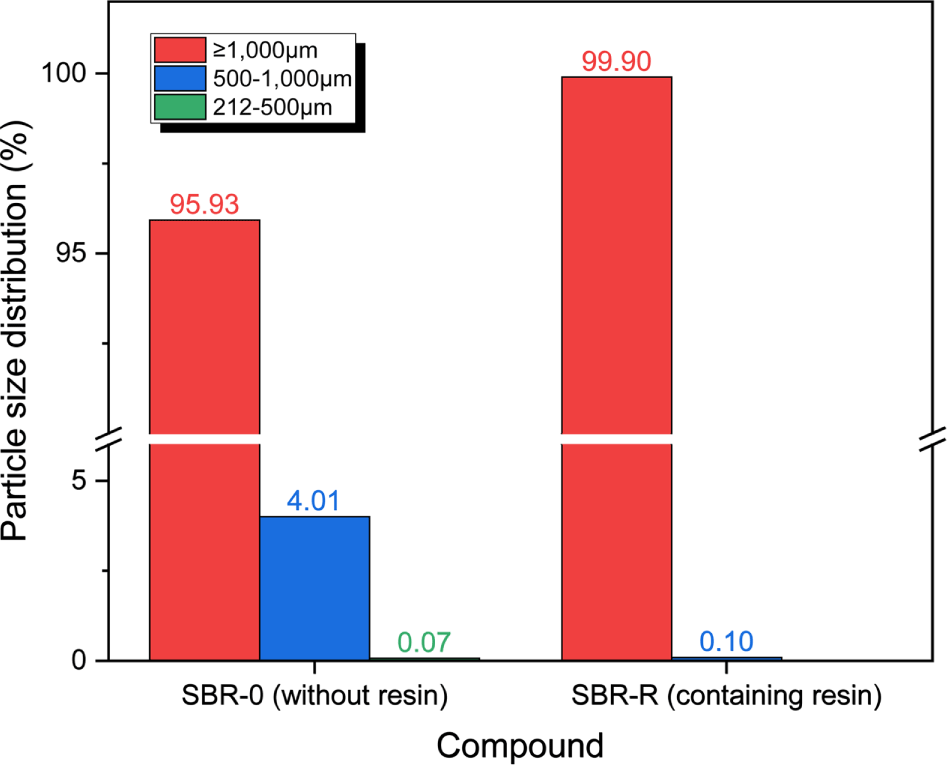
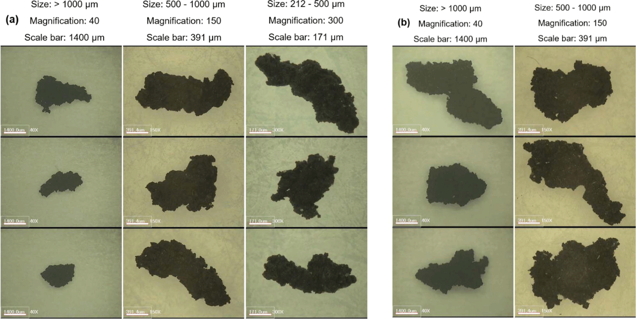
Size distributions of the wear particles produced through the CC abrasion test are shown in Figure 1. Most wear particles had size of larger than 1000 μm (over 95%), particularly, the SBR-R sample had 99.9% of the large wear particles. This may be due to the low moduli. Shift of the wear particle size distribution to larger size can lead to large amount of abrasion. Figure 2 shows the magnified images of the wear particles produced from the SBR-0 and SBR-R samples by the CC abrasion test. The wear particles had rough surface and there were no inorganic particles on the surface. For the wear particles larger than 1000 μm, the sizes of wear particles produced from the SBR-R sample were larger than those produced from the SBR-0 sample. This may be due to the worse physical properties of the SBR-R sample compared to the SBR-0 sample.
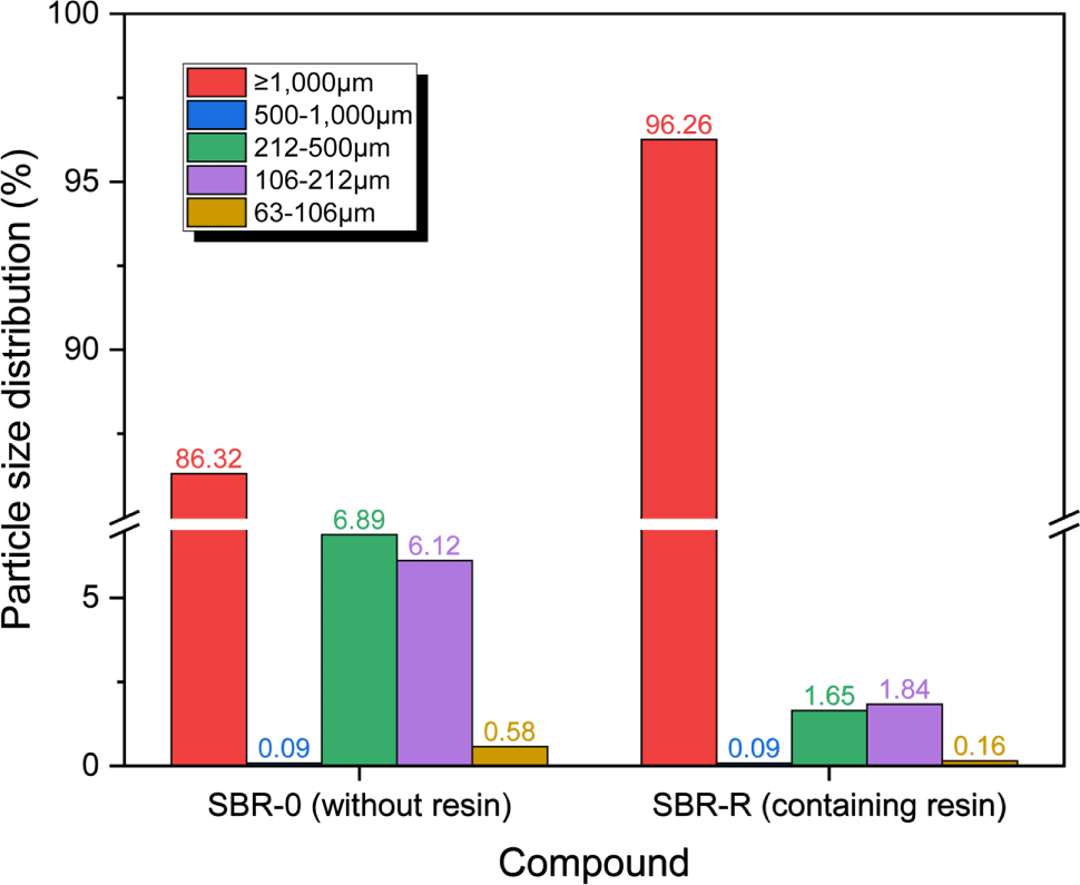
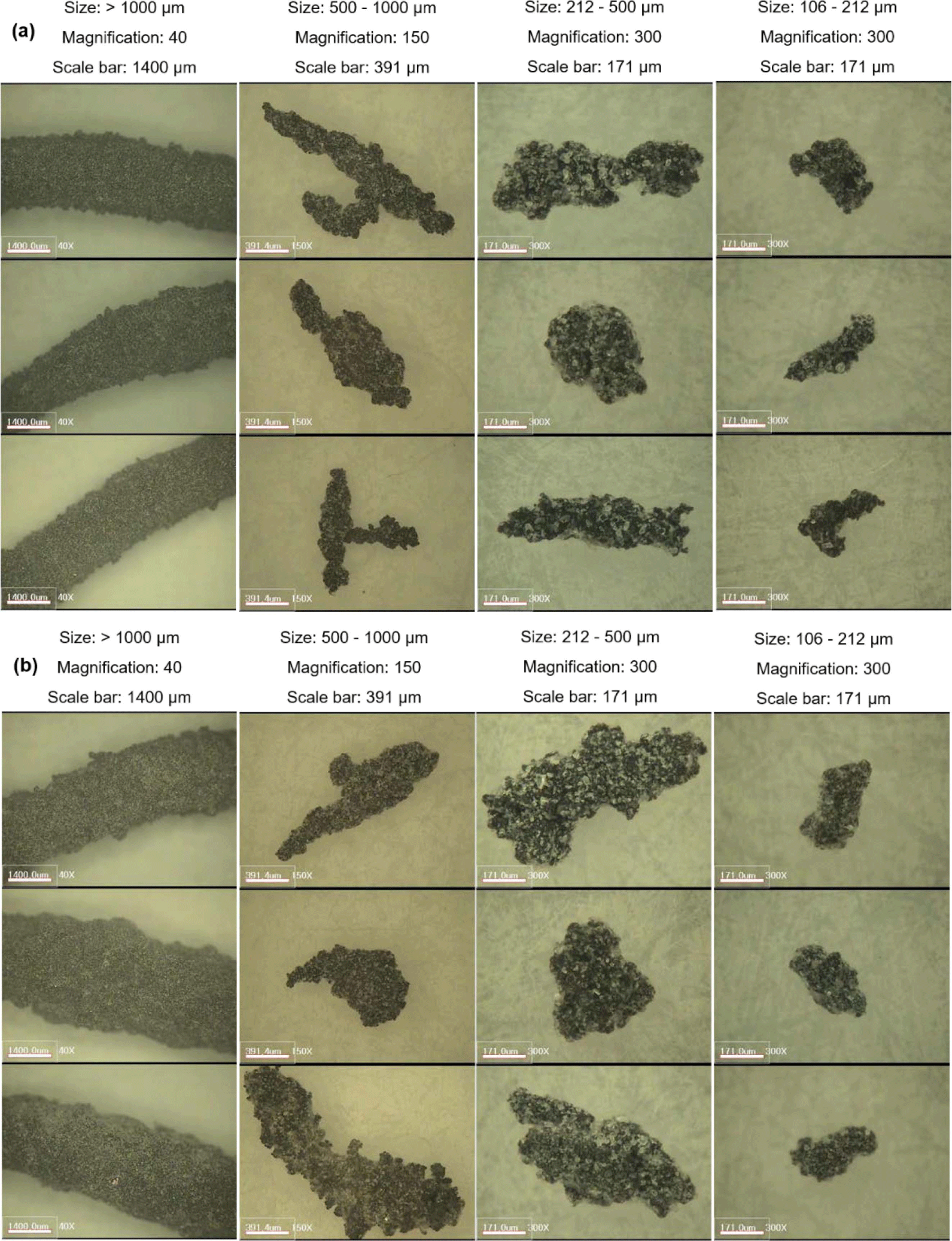
Size distributions of the wear particles generated from the Lambourn abrasion test are shown in Figure 3. Most wear particles had size of larger than 1000 μm; the size distributions of wear particles larger than 1000 μm were 83 and 93% for the SBR-0 and SBR-R samples, respectively. Very small wear particles of 63-106 μm were also observed, but their distributions were very low (> 1%). There was an interesting result; the size distributions of wear particles of 500-1000 μm were negligible (> 0.1%). Figure 4 shows the magnified images of the wear particles produced from the SBR-0 and SBR-R samples by the Lambourn abrasion test. The wear particles obtained by the Lambourn abrasion test showed less rough surface than those obtained by the CC abrasion test. The wear particles obtained from the Lambourn abrasion test had a lot of talc powder on the surface. The aspect ratios of the wear particles produced from the SBR-0 sample were relatively higher than those produced from the SBR-R sample. This may be due to the worse moduli and tensile strength of the SBR-R sample compared to the SBR-0 sample. The worse physical properties of the SBR-R sample can lead to higher production of the large wear particles.
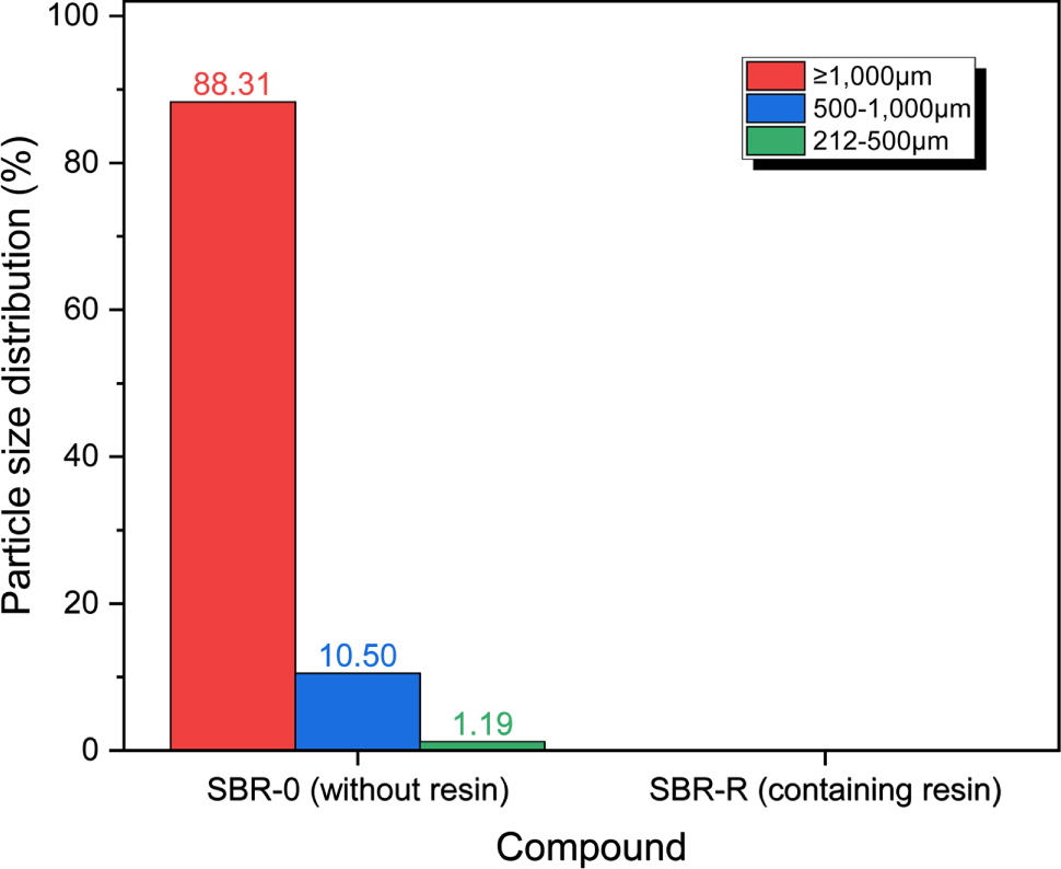
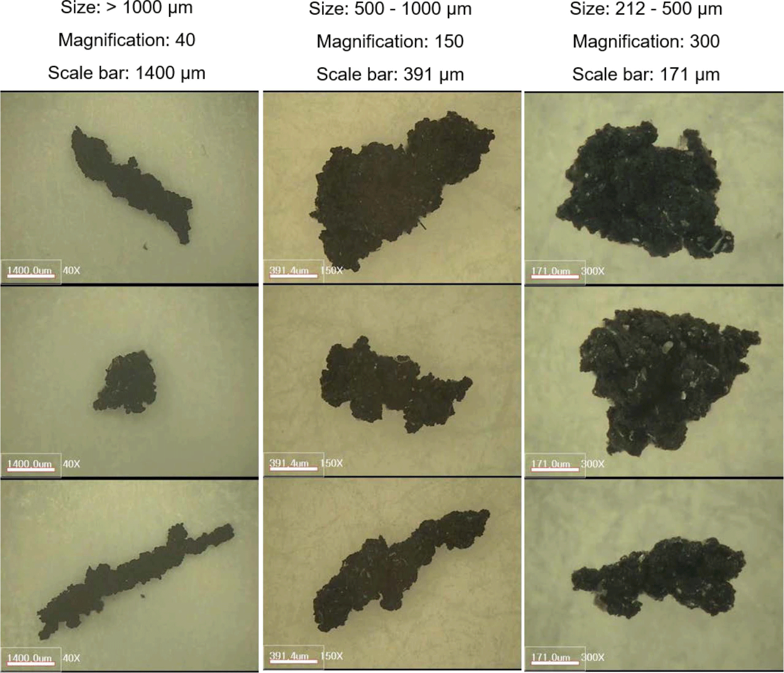
The DIN abrasion test for the SBR-R sample was not successfully performed because the abrasion sample was departed from the zig at the beginning of the abrasion test. This may be due to the high elongation at break and the slippery surface of the abrasion specimen owing to the high loading of oil (19 phr) and addition of resin (20 phr). Size distribution of the wear particles produced from the SBR-0 sample by the DIN abrasion test is shown in Figure 5. Most wear particles had size of larger than 1000 μm, but the distribution (88%) was lower than that for the CC abrasion test (96%). The wear particles smaller than 212 μm were not observed. Figure 6 shows the magnified images of the wear particles produced from the SBR-0 sample by the DIN abrasion test. The wear particles had rough surface, and the aspect ratio tended to decrease by decreasing the particle size. There were some inorganic particles on the wear particle surface with size of 212-500 μm. The tiny inorganic particles came from abrasion of the sandpaper.
Size distributions of the wear particles produced by the LAT100 abrasion test are shown in Figure 7. The wear particle size distributions of the two samples showed very different trends. For the SBR-0 sample, most wear particles had size of larger than 1000 μm (83%), and the wear particles were observed until the size of 212 μm. For the SBR-R sample, the wear particles were distributed in a wide range from 63 μm to larger than 1000 mm, and the most distribution was 500-1000 μm (38%). The size distribution of wear particles of 212-500 μm (32%) was higher than that of wear particles larger than 1000 μm (26%). Among the four abrasion testers, the size distribution of wear particles larger than 1000 μm produced by the LAT100 abrasion test was the lowest. For the wear particles larger than 1000 μm, the distribution of the SBR-0 sample was much higher than that of the SBR-R sample by over 3 times, which was the opposite result to the CC and Lambourn abrasion tests.
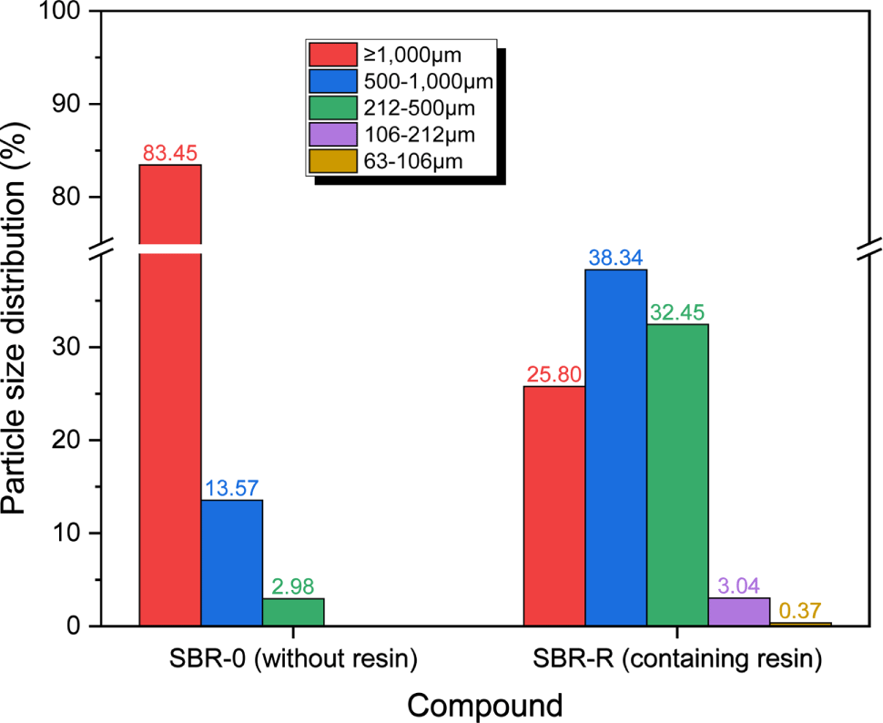
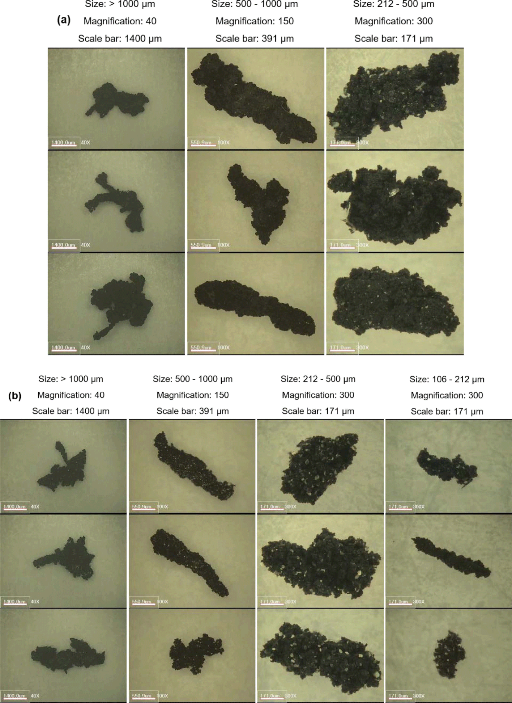
Figure 8 shows the magnified images of the wear particles produced from the SBR-0 and SBR-R samples by the LAT100 abrasion test. The wear particles had rough surface, and there were some inorganic particles on the wear particles smaller than 500 μm. The tiny inorganic particles originated from the sandpaper by friction with the abrasion specimen. The wear particles larger than 1000 μm showed branched structures, while those of 500-1000 μm had stick-like structures overall. The wear particles of 212-500 μm showed rougher surface than the other-sized wear particles and had relatively smaller aspect ratio. The number of inorganic particles on the wear particle produced from the SBR-R sample was more than that on the wear particle generated from the SBR-0 sample.
Addition of the resin influenced on the abrasion behavior, but the effect varied depending on the abrasion tests. By adding the resin, the wear particle surface became less rough but the abrasion rate was not improved except for the Lambourn abrasion test. Except for the LAT100 abrasion test, the wear particle size distribution was shifted to the large size by adding the resin.
Conclusions
By adding the resin, the abrasion rate and the size distribution and morphology of wear particles were influenced. The order of abrasion rate according to the abrasion tester was CC > Lambourn > LAT100. For the CC and LAT100 abrasion tests, the abrasion rate of the SBR-0 sample was lower than that of the SBR-R sample, whereas for the Lambourn abrasion test, the former was higher than the latter. For the CC abrasion test, most wear particles had size of larger than 1000 μm (over 95%) and the wear particles had rough surface. For the wear particles larger than 1000 μm produced by the CC abrasion test, the sizes of wear particles produced from the SBR-R sample were larger than those of the SBR-0 sample. For the Lambourn abrasion test, there were a lot of talc powder on the wear particle surface and the size distributions of the wear particles larger than 1000 μm were 83 and 93% for the SBR-0 and SBR-R samples, respectively. The wear particles obtained by the Lambourn abrasion test had less rough surface than those obtained by the CC abrasion test. For the DIN abrasion test of the SBR-0 specimen, most wear particles had size of larger than 1000 μm and there were some inorganic particles on the wear particle surface with size of 212-500 μm, but the wear particles smaller than 212 μm were not observed. For the LAT100 abrasion test, for the SBR-0 sample, most wear particles had size of larger than 1000 μm and the wear particles were observed until the size of 212 μm, while for the SBR-R sample, the wear particles were distributed in a wide range from 63 μm to larger than 1000 μm and the most distribution was 500-1000 μm. The wear particles produced from the LAT100 abrasion test had rough surface and there were some inorganic particles on the wear particles smaller than 500 μm. The wear particles larger than 1000 μm showed branched structures, while those of 500-1000 μm had stick-like structures overall.