Introduction
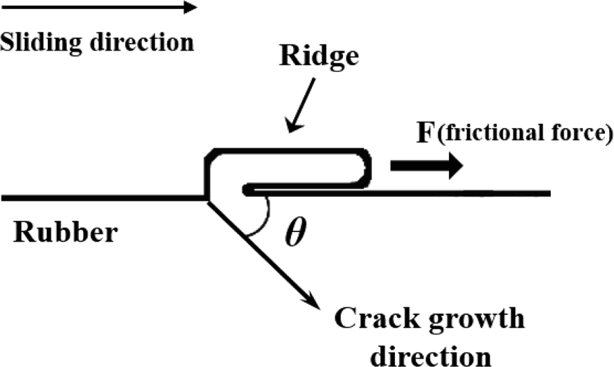
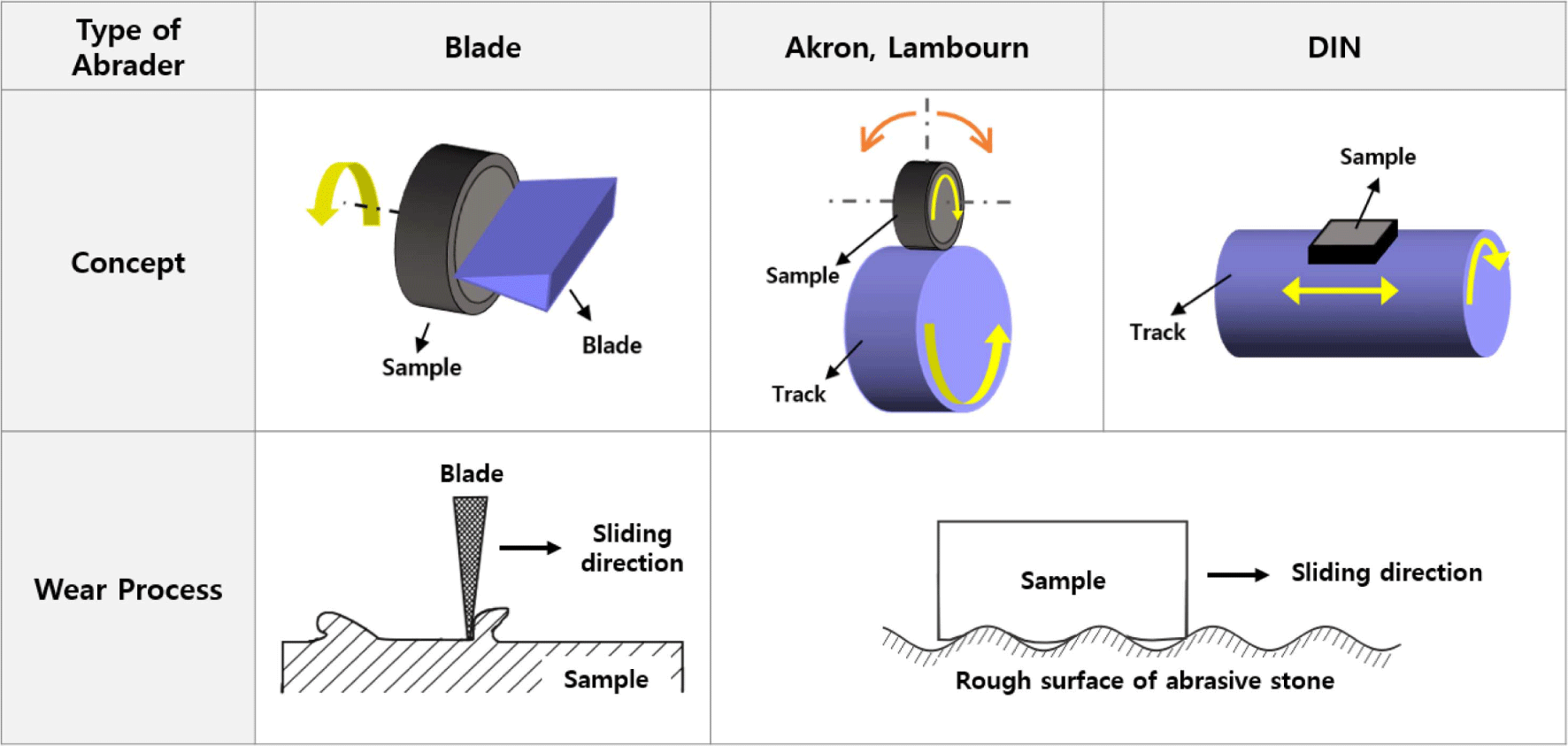
Rubber materials are used in a variety of product applications across different fields, including automotive, footwear, construction, aerospace, electronics, medical devices, sports equipment, and consumer goods, due to their unique visco-elastic properties such as high elasticity and high stretchability.1,2 To achieve the required performance in different product applications, reinforcing fillers are added to rubber materials.3-5 Carbon black and silica are commonly used as reinforcing fillers. The preference for silica is being increased due to the demand for products in various colors.6-8 Especially in the tire market, which accounts for most of the world’s rubber consumption, research into the development of eco-friendly tires using silica with excellent fuel efficiency properties, is actively being conducted, as environmental concerns have increased dramatically in recent years.9-12 The friction and wear performance of rubber products like tires which are usually used under harsh conditions such as high loads and temperatures, are crucial for product stability. However, this may vary depending on the type of reinforcing fillers, particle size, and degree of structure development.13-17 The wear of rubber materials is a complex phenomenon influenced by various factors including; nature of matrix and reinforcing fillers, particle size, and degree of structure etc.16,17 The wear mechanism of elastomeric compounds has been greatly explored with interesting findings by various researchers like Schallamach,18 Grosch,19 Gent,20 and Thomas.21 For instance, it has been established that, when a rubber material is subjected to repeated friction, a ridge is formed perpendicular to the rubber sliding direction, as shown in Figure 1, and wear occurs as a result of the continuous frictional force applied to the ridge. This wear mechanism is known as pattern wear or fatigue wear, and it has been confirmed that there is a correlation between fatigue properties and wear properties. Cracks between the wear patterns gradually grow due to repeated friction and eventually leads to the rubber particles separating from the rubber specimen, which is similar to the crack growth model under mechanical fatigue.14,22,23 Various wear testing methods have been developed to predict the wear properties of rubber materials, where frictional force is applied to the specimen by a rough abrasive surface or a sharp blade. The blade-type, Lambourn, Akron, and DIN abraders are already reported models of wear testing methods (Figure 2).16,23-26 The blade-type abrader in which the rotating rubber surface is scraped by the blade under given pressure determines the wear rate by measuring the weight lost or the thickness reduction of the rubber speci-men.23,24,26 Lambourn and Akron abraders are wheel type abrader where a rubber wheel runs on the rotating abrasive surface under slip condition.25 The DIN abraders on the other hand, is a rotary drum abrasion tester in which the rubber is sliding on a rotating cylinder covered with the abrasive paper. Thus, the Lambourn, Akron and DIN abraders have been used to evaluate wear properties by measuring the weight lost to wear.16,25
It should be noted that the wear properties of rubber materials are crucial for determining the service life of rubber products; hence it is important to carefully examine and accurately predict the different factors which could influence the overall wear performance of a rubber compound.
In this current study, Silica/SBR based compounds were prepared by melt mixing method with five different types of silica, having different particle sizes and structure. The wear performance was evaluated using blade-type abrader and Akron abrader. The relation between the measured wear behavior and the compensated characteristic parameter (Ψc) originating from the particle size, and the structural effect of the fillers was established.
Experimental
Styrene-butadiene rubber (SBR, SOL 6361H, styrene content: 33 wt%, vinyl content: 58 wt%) of Kumho Petrochemical was used. Five types of silica having different particle size and structure was used as reinforcing fillers, they include: Z1115 (Zeosil 1115MP, Solvay), VN3 (ULTRASIL VN3, Evonik), Z175 (Zeosil 175 GR, Solvay), U7000 (ULTRASIL 7000GR, Evonik), and SDP20 (Fusil SDP20, Fuchangchem). Sulfur served as the curing agent, while Si-69 was used as the silane coupling agent. The other compounding ingredients were zinc oxide (ZnO), stearic acid (S/A), N-tert-Butyl benzothiazole-2 sulfenamide (NS), paraffinic oil (P-3) and Poly (1,2-dihydro-2,2,4-trimethylquinoline) (RD). The particle size and structure of the silica fillers were determined based on N2 adsorption (m2/g) and dibutyl phthalate (DBP) absorption (ml/100 g), respectively. Table 1 and Figure 3 show the N2 adsorption and DBP absorption for the five types of silica used in this study.
| Type of Silica | Z1115 | VN3 | Z175 | U7000 | SDP20 |
|---|---|---|---|---|---|
| N2 (m2/g) | 108 | 161 | 165 | 167 | 200 |
| DBP (ml/100 g) | 165 | 182 | 208 | 250 | 220 |
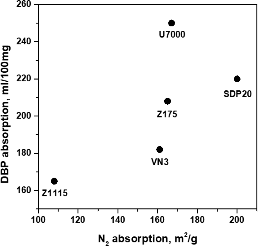
Table 2 shows the recipe for the rubber compounds used in this study. The mixing of rubber compounds was carried out in a Banbury mixer (NamYang Enterprise Co. Ltd., Korea) for 1 minute at 150°C with 50 rpm. Silica, Si69, RD, P-3, ZnO, and S/A were sequentially added and mixed for 6 minutes. The curing agent and accelerator were blended into master batches using a two roll mill (DS-1500R, WITHLAB Co. Ltd., Korea) for 10 minutes. The cure time (t90) was determined using a cure rheometer (Oscillating rheometer, ODR, AlphaTechnology, UK) at 170°C, and the rubber specimens were finally cured using a hydraulic press (CMV50H-15-CLPX, Carver, Inc., USA) at 170°C for t90. The cured rubber specimens were cut into standard sizes and dimensions for further characterizations.
| SBR | Silica | Si-69 | ZnO | aS/A | bRD | cP-3 | dNS | Sulfur |
|---|---|---|---|---|---|---|---|---|
| 100 | 50 | 4 | 3 | 1 | 1 | 1 | 1 | 2 |
The Young’s modulus was calculated by measuring the strain of the rubber specimen having a rectangular shape with dimensions of 5 × 50 × 2 (mm), by applying load to the rubber specimen.
The rubber specimens for the blade-type abrader were cylindrical with a central void, as shown in Figure 4, to facilitate the emission of frictional heat during the wear process. A schematic representation of the blade-type abrader used in this study is shown in Figure 5. Perpendicular load was applied on to the rubber specimen through the blade, and the load was controlled by using different weights (3 to 5 kg). Zirconia blades were utilized. The rotation speed and the temperature were set at 10 rpm and at 30 °C, respectively. Preliminary abrasion was conducted until a consistent wear pattern formed on the specimen surface and the torque value remained constant. Subsequently, the main wear test was carried out with a new blade. The wear characteristics were evaluated by measuring the wear rate according to the frictional energy which was produced between the surface of a rotating rubber specimen and blade. The frictional energy, Wf, can be calculated using Equation (1);
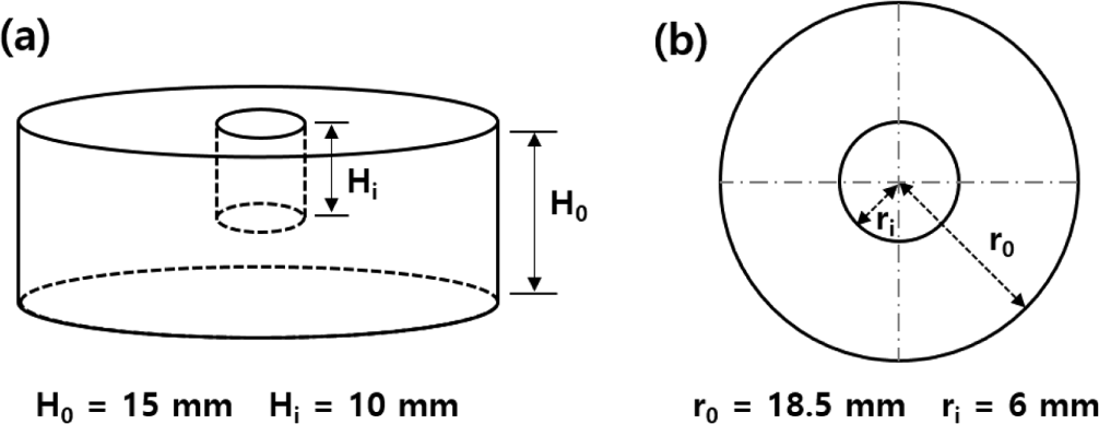
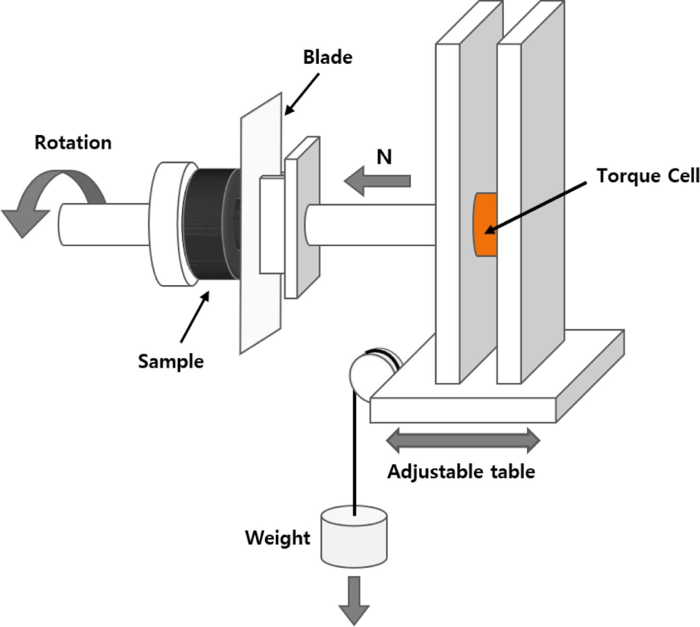
where M is the frictional torque, r0 is the outer radius of the specimen (18.6 mm), and ri is the inner radius of the specimen (5.9 mm). The frictional torque was measured by a torque sensor attached to the blade axis. The wear rates were defined by Rh and Rw, which respec-tively relates to the change in height (mm) and the loss in weight (g) of rubber specimen, for one rotation of the rubber specimen around its axis. The wear rates, Rh and Rw, were given by:
where L is the displacement of the blade axis during abrasion, n is the number of revolutions and T is the weight loss of the rubber specimen during abrasion.
The wear characteristic using Akron abrader was measured based on the KS M6624 standard. A specimen with a diameter of 63.5 mm, a thickness of 12.7 mm, and a central hole with a diameter of 12.7 mm was positioned on a grinding wheel at a 25° contact angle. The test was carried out at 2000 rpm with a 5 kg load. The wear properties were evaluated by measuring the wear loss volume corresponding to 1000 revolutions of the grinding wheel, as defined in Equation (4);
where T0 is the initial mass (g) of the rubber specimen before the wear test, Tn is the mass (g) of the rubber specimen after the wear test, and ρ is the density (g/cm3) of the rubber specimen.
Fatigue fracture properties were evaluated by measuring the crack growth rate of the rubber specimens as a function of the tearing energy. The tearing energy, G, can be calculated using the Griffith relation, as shown in Equation (5).
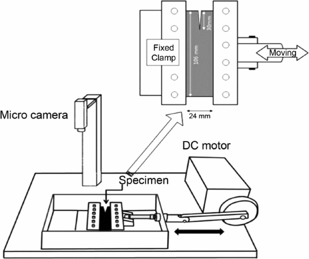
Here, U is the strain energy density, which was taken as the area under the unloading stress-strain curves of a pure shear specimen without pre-cut at a specific strain. h0 is the initial height of the rubber specimen. Figure 6 shows a schematic diagram of dynamic fatigue instrument for measuring the fatigue failure behaviors. A rubber specimen with a thickness of 2 mm and dimensions of 106 × 24 mm with a pre-cut of 30 mm was prepared for the measurement of the crack growth rate. The crack growth rate (dc/dn) of the rubber specimen was obtained from the slope of the graph of the crack growth length (c) as a function of the number (n) of repeated deformation applied to the rubber specimen. The strain (ε) applied to the rubber specimen was adjusted within the range of 0.12 to 0.35.
Results and Discussion
The particle size and structure of the filler affect the mechanical properties such as the Young’s modulus, tensile strength, and tearing strength of rubber compounds.17,27,28 In the case of carbon black, the characteristic parameter (Ψ) originated from the particle size and the structure of fillers shows a close relationship with the Young’s modulus and the wear rate of rubber compounds.17 the characteristic parameter of carbon black, Ψ, is defined in equation (6) by.
Here, N2 is the nitrogen adsorption on the surface of carbon black, related to the particle size, while DBP is the dibutyl phthalate adsorption which is also related to the indicated structure of carbon black. The idea in equation (6) for carbon black was adopted to model the characteristic parameter, Ψ of silica. The relationship between the calculated Ψ for silica and the Young’s modulus of Silica/SBR compounds is shown in Figure 7. The Young’s modulus increased with increasing the characteristic parameter of silica, which implies that the smaller the particle size and the more developed or intricate the structure of silica is, the greater the reinforcing effect on the compounds and hence the higher the corresponding Young’s modulus. Thus, a linear relationship between the Young’s modulus and the characteristic parameter of silica was observed, as shown in Figure 7 (Equation 7);
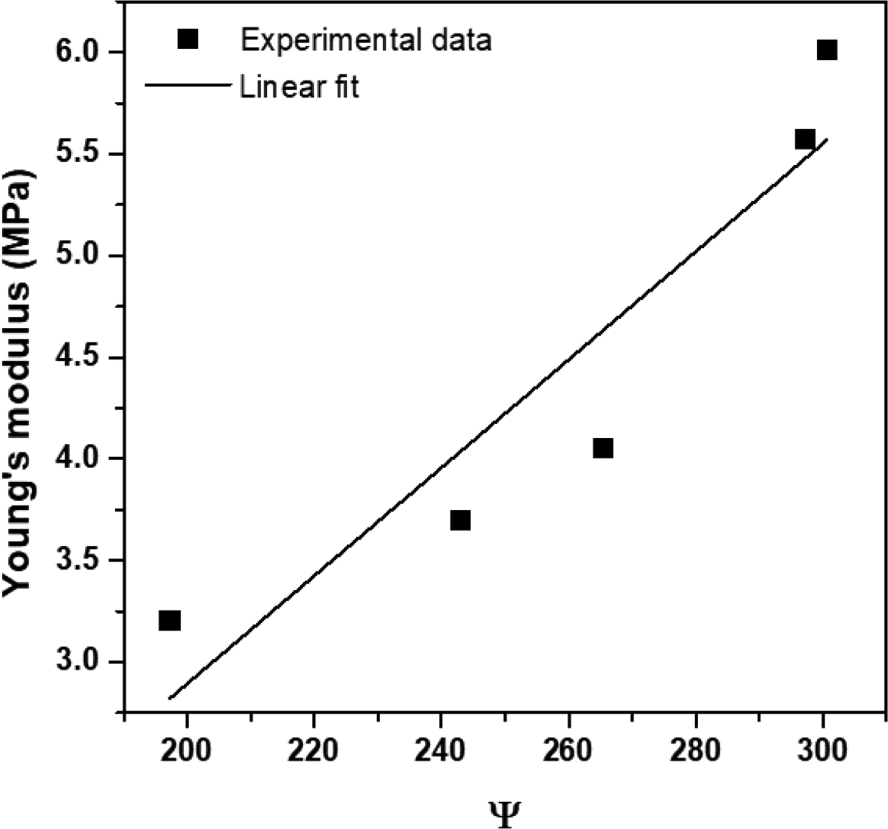
where a and b are constants and E is the Young’s modulus. The coefficient of determination, R2, was used to predict how the Young’s modulus and the characteristic parameter of silica are statistically correlated. The R2 was somewhat lower at 0.865, due to slight scattering of data. The particle size and structure of the filler in relation to the characteristic parameters, Ψ, was initially selected to be in a 1:1 ratio. However, it was considered that the contribution of the particle size and structure of the filler were different with regards to the mechanical properties of the rubber compounds. Therefore, equation (6) was re-modeled by introducing a compensated characteristic parameter, Ψc, which takes into account the different contributory effects of the particle size and structure of the filler, as defined in equation (8);
where A and B are the respective contributory factors of particle size and the structure effect of silica. The values of A and B were chosen between 0.1 and 0.9, depending on the ratio that reflects N2 and DBP, with A+B=1. The compensated characteristic parameters of the five different types of silica based on the values of A and B, have been presented in Table 3. The compensated characteristic parameters increased in the order of Z1115 < VN3 < Z175 < SDP20 < U7000, but a reversed trend was observed for SDP20 and U7000 when the value of A was above 0.6. The Young’s modulus as a function of the compensated characteristic parameters of the Silica/SBR compounds is shown in Figure 8. The Young’s modulus increased with increasing compensated characteristic parameter of silica. A linear relationship between the Young’s modulus and compensated characteristic parameter of silica was observed, as shown in Equation (9);
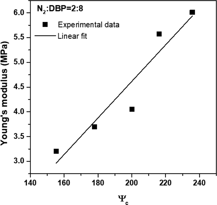
where c and d are constants. The relationship between the Young’s modulus and the compensated characteristic parameter in all ranges of values of A and B (A, B = 0.1~0.9, A+B=1) followed Equation (9), and the values of R2 between the Young’s modulus and compensated characteristic parameter for the corresponding values of A and B are shown in Table 4. The values of R2 were found to be between 0.619 and 0.912 and it increased with increasing of the structure effect (B) of silica.
| N2:DBP | 1 : 9 | 2 : 8 | 3 : 7 | 4 : 6 | 5 : 5 | 6 : 4 | 7 : 3 | 8 : 2 | 9 : 1 |
|---|---|---|---|---|---|---|---|---|---|
| A | 0.1 | 0.2 | 0.3 | 0.4 | 0.5 | 0.6 | 0.7 | 0.8 | 0.9 |
| B | 0.9 | 0.8 | 0.7 | 0.6 | 0.5 | 0.4 | 0.3 | 0.2 | 0.1 |
| R2 | 0.907 | 0.912 | 0.908 | 0.893 | 0.865 | 0.823 | 0.767 | 0.698 | 0.619 |
Clearly, it seems that the Young’s modulus of the Silica/SBR compound was more influenced by the structure effect than the particle size of silica effect. Additionally, the value of R2 was observed to be the highest 0.912 when A and B were 0.2 and 0.8 respectively. It can therefore be concluded that the Young’s modulus of Silica/SBR compounds have stronger correlation with the compensated characteristic parameters, Ψc, as compare to the uncompensated characteristic parameters, Ψ.
The wear properties of Silica/SBR compounds with the various types of silica were measured using a blade-type abrader. The logarithmic plots of the wear rates (Rh and Rw) against the frictional energy have been shown in Figure 9 for silica-filled SBR compounds containing different types of silica. As clearly seen, as the frictional energy increased, both Rh and Rw also increased, that is a ‘Power-Law’ relationship between the wear rate and frictional energy was established as shown in Equation (10);
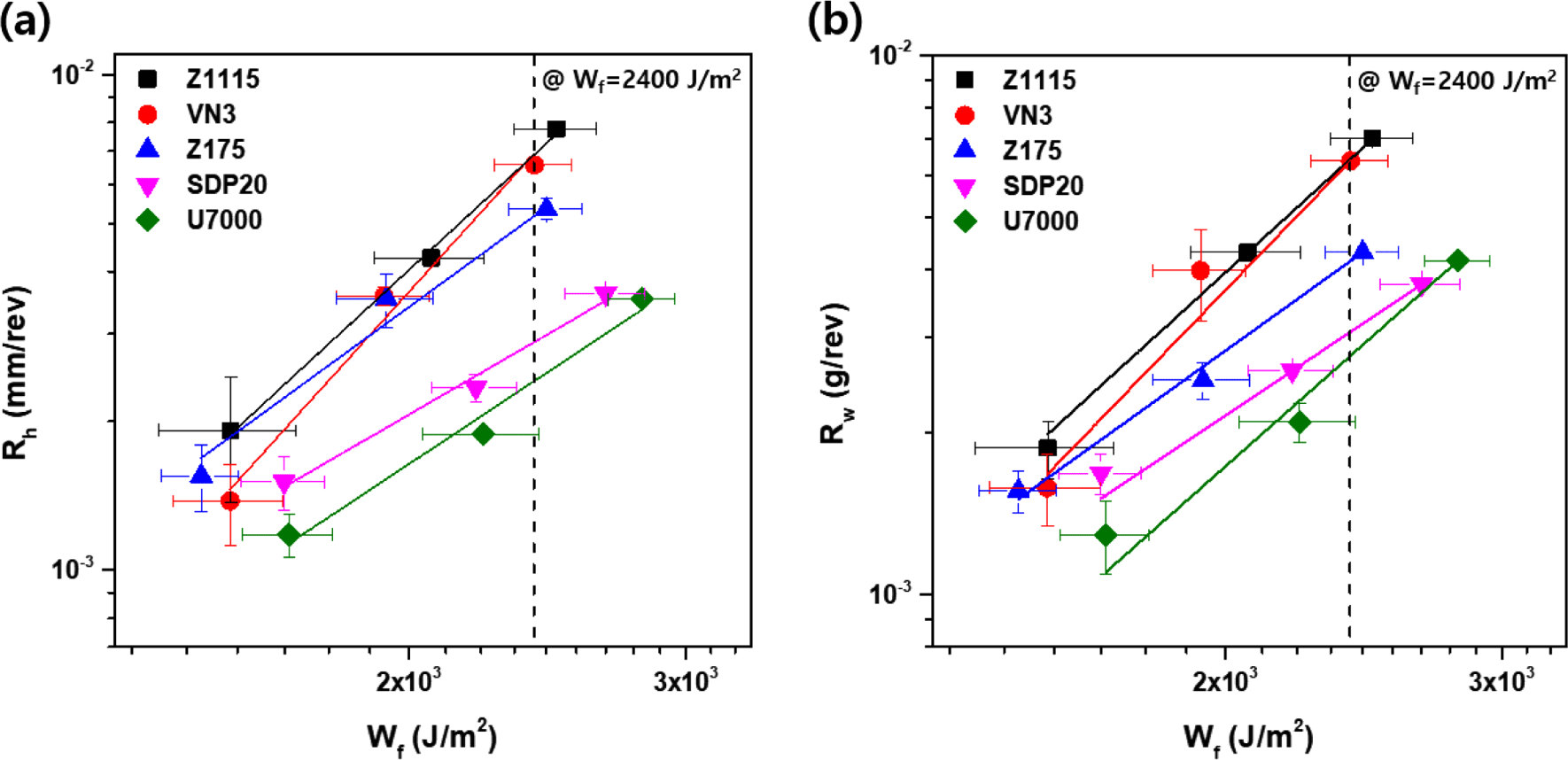
where k and n are constants. To establish the relationship between the wear rate (Rh, Rw) and the compensated characteristic parameters of silica, the wear rate at a specific frictional energy was employed. A specific frictional energy was selected to be 2,400 J/m2 (Figure 9), which is the frictional energy under the same conditions as the load (5 kg) applied to Akron wear test. The wear rates of silica filled-SBR compounds containing the different types of silica at 2,400 J/m2 are shown in Table 5. It was interesting to observe that the wear rate varied depending on the type of silica. The order of increment was observed to be: U7000 < SDP20 < Z175 < VN3 < Z1115. Also depicted in Figure 10 is the relationship between the wear rate at 2,400 J/m2 of the friction energy and the compensated characteristic parameters. As the compensated characteristic parameter increased, the wear rate appeared to be decreasing, indicating that the smaller the particle size and the more developed the structure of silica, the more the wear resistance is seen to be improved. Thus, an inverse relationship between the wear rates and compensated characteristic parameters of silica was observed, as shown in Figure 10 and Equation (11);
| Type of Silica | Z1115 | VN3 | Z175 | U7000 | SDP20 |
|---|---|---|---|---|---|
| Rh (10-3 mm/rev) | 6.88 | 6.57 | 5.18 | 2.41 | 2.88 |
| Rw (10-3 g/rev) | 6.41 | 6.35 | 4.15 | 2.77 | 3.07 |
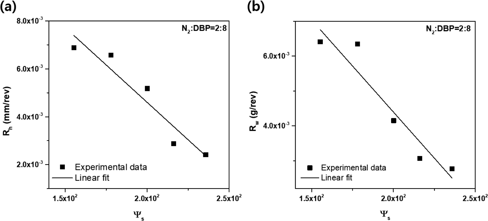
where e and f are constants. The ranges of values of A and B (A, B=0.1~0.9, A+B=1), was selected to compute the relationship between the wear rate and compensated characteristic parameter by using Equation (11). The values of R2 between the wear rate and compensated characteristic parameter based on the values of A and B are shown in Table 6. The values of R2 of Rh and Rw with respect to the compensated characteristic parameter were found to be 0.613~0.913 and 0.616~0.910, respectively. It was interesting to observe that these ranges of values showed similarities at the same values of A and B. In addition, the R2 tends to increase as the contributory factor (B) related to the structure effect of silica, increased.
Consequently, wear rate of the Silica/SBR compound measured by the blade-type abrader appeared to be affected more by the structure effect than the particle size effect of the silica. The R2 values of Rh and Rw for the compensated characteristic parameter were highest at 0.913 and 0.910, respectively, when A=0.2 and B=0.8, exhibiting a similar behavior as observed for the case of the Young’s modulus.
In order to investigate the correlation between the wear resistance and fatigue failure resistance of Silica/SBR composites based on the silica type, the crack growth rate (dc/dn) of Silica/SBR composites was measured and the logarithmic plot of the crack growth rate (dc/dn) against tearing energy (G) has been presented in Figure 11. It was found that the crack growth rate tends to increase linearly with the increase of tearing energy. This followed a ‘Power-Law’ relationship (Equation 12), similar to that observed for the case of the wear properties.
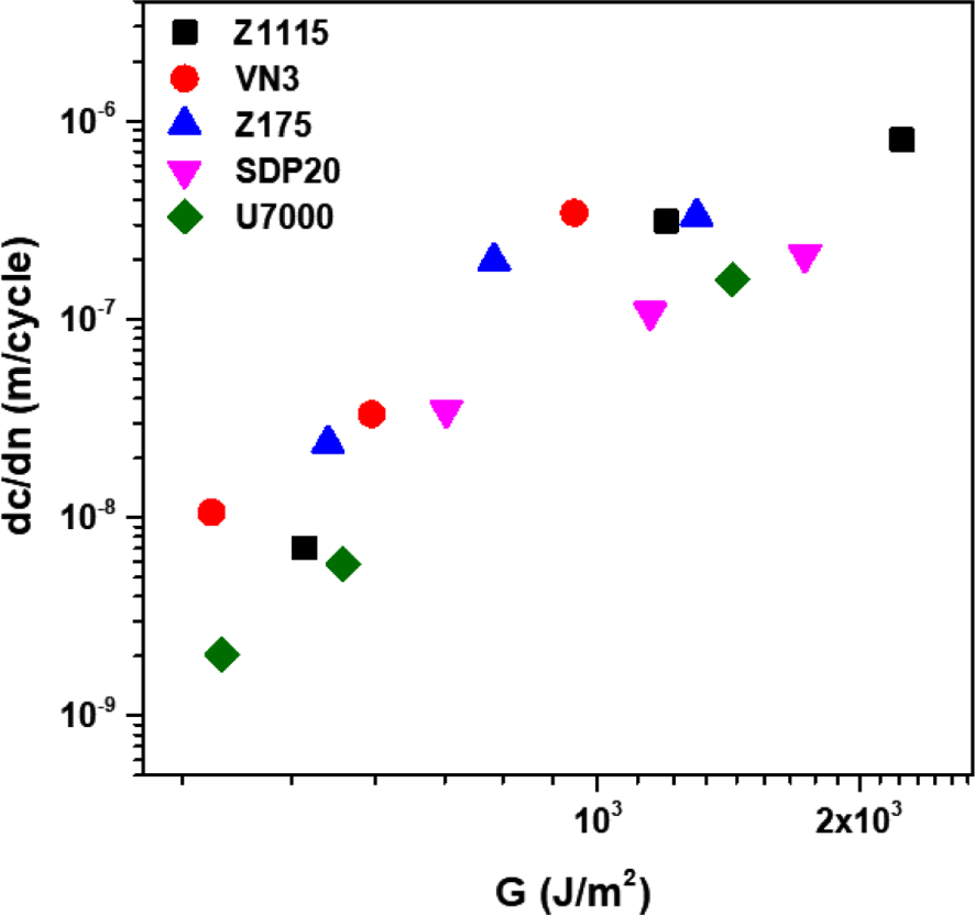
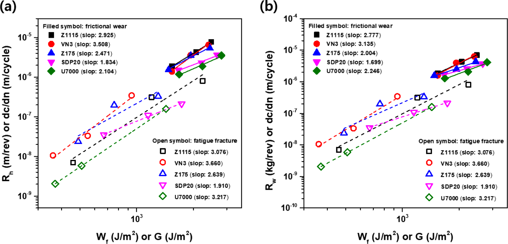
In Figure 12, the wear (Rh or Rw vs Wf) and fatigue fracture properties (dc/dn vs G) were also plotted on the same range of scales. Here, it can be seen that the wear and fatigue data showed a high correlation with similar slopes and energy distributions, and the wear data was closely related to Rh while the Rw also showed a more closely related slope as the fatigue data.
The wear properties of the specimen conducted using the Akron abrader were evaluated by measuring the volume loss per 1000 revolutions (cm3/1000rev), as presented in Table 7. The observed order of increment in wear loss volume based on the type of silica can be written as: SDP20 < U7000 < VN3 < Z1115 < Z175. Comparatively, this differed somewhat from the wear behaviors evaluated using the blade-type abrader. The volume loss as a function of the compensated characteristic parameters for silica filled-SBR compounds containing different types of silica has been shown in Figure 13. Although, small scattering in data can be observed, however, there was a decline in the volume loss of Silica/SBR compounds measured with the Akron abrader as the compensated characteristic parameters increased. As shown in Figure 13, the volume loss followed an inverse relationship with the compensated characteristic parameters (Equation 13).
| Type of Silica | Z1115 | VN3 | Z175 | U7000 | SDP20 |
|---|---|---|---|---|---|
| Volume loss (10-2 cm3/1000rev) | 6.96 | 5.81 | 7.05 | 3.64 | 3.60 |
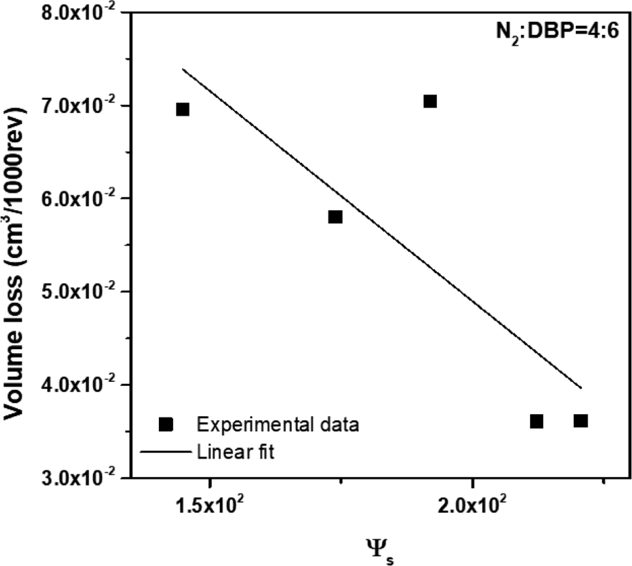
where g and h are constants. The relationship between the volume loss and compensated characteristic parameters for all ranges of A and B (A, B=0.1~0.9, A+B=1) is represented, as shown in Equation (13). Table 8 shows the R2 values between the volume loss and the compensated characteristic parameters based on the values of A and B. The R2 values were in range of 0.533 to 0.649 depending on the values of A and B. Here, the R2 values of the volume loss against the compensated characteristic parameters were generally lower compared to that of the wear rate that was measured with the blade-type abrader. Furthermore, in contrast to the Young’s modulus and the wear rate data measured with the blade-type abrader, the highest R2 value of 0.649 was observed at A=0.4 and B=0.6 respectively.
| N2:DBP | 1 : 9 | 2 : 8 | 3 : 7 | 4 : 6 | 5 : 5 | 6 : 4 | 7 : 3 | 8 : 2 | 9 : 1 |
|---|---|---|---|---|---|---|---|---|---|
| A | 0.1 | 0.2 | 0.3 | 0.4 | 0.5 | 0.6 | 0.7 | 0.8 | 0.9 |
| B | 0.9 | 0.8 | 0.7 | 0.6 | 0.5 | 0.4 | 0.3 | 0.2 | 0.1 |
| R2 | 0.610 | 0.628 | 0.642 | 0.649 | 0.647 | 0.635 | 0.612 | 0.578 | 0.533 |
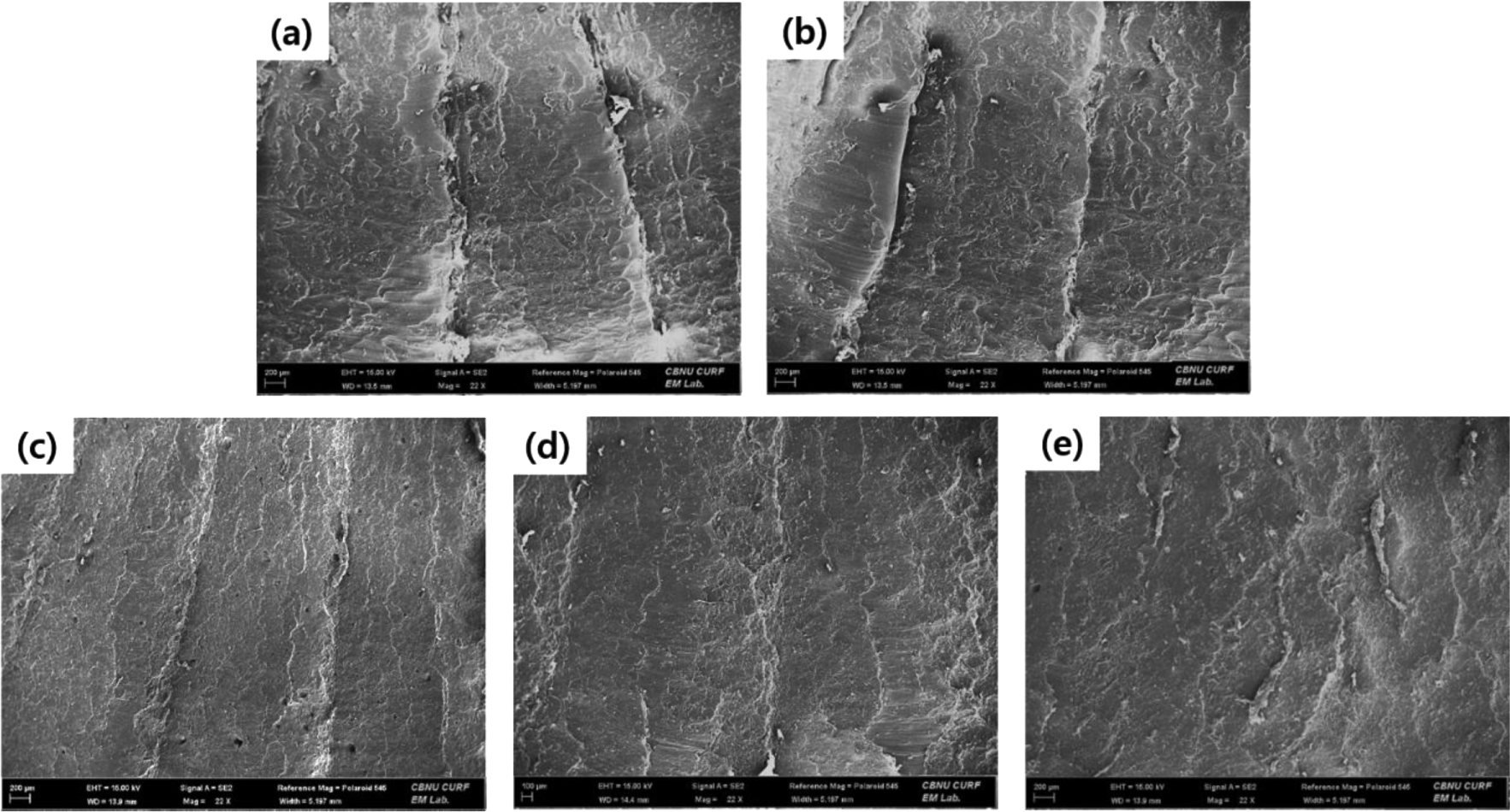
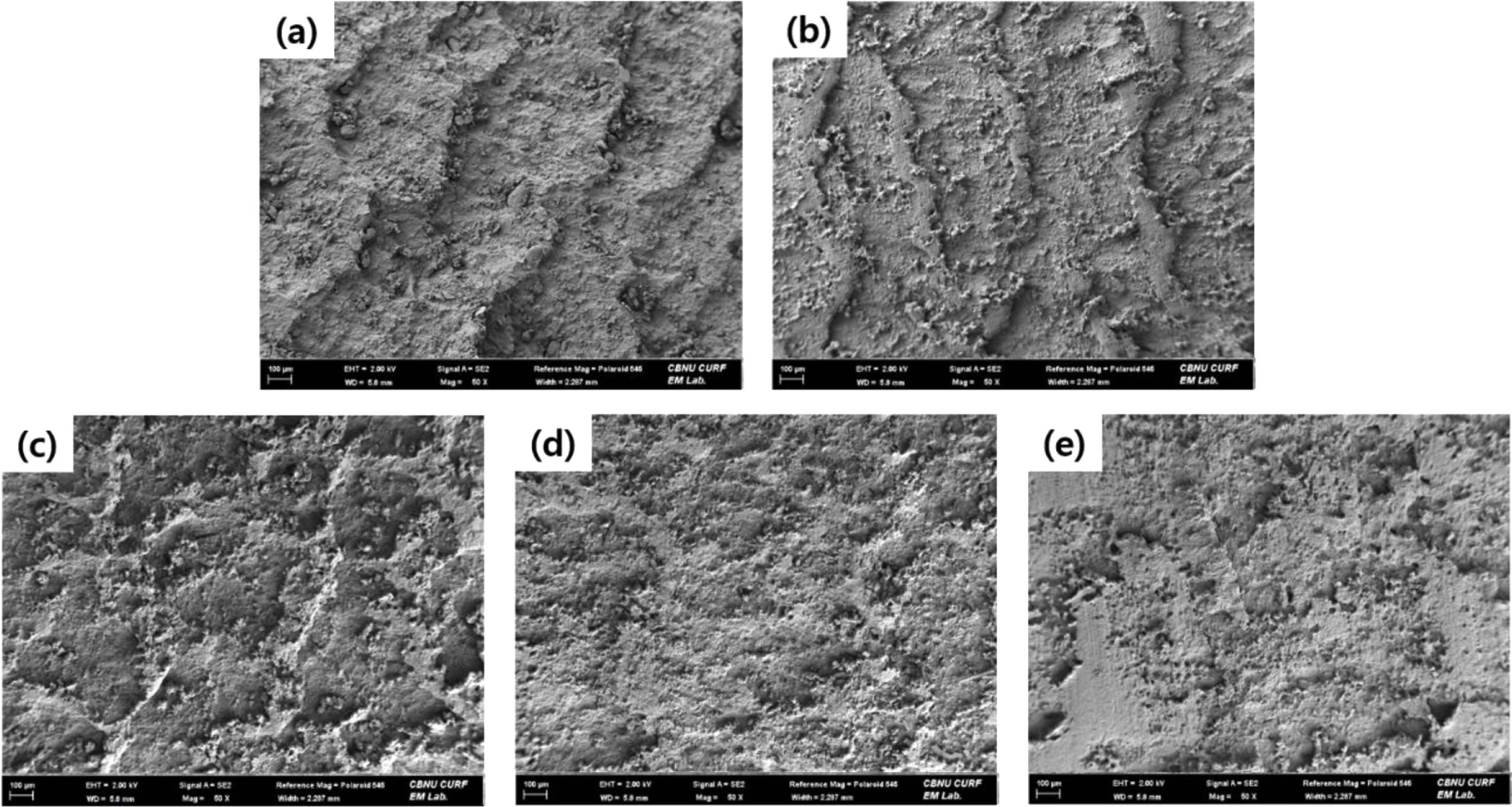
Generally, the pattern and roughness of the worn surface depends on the wear behavior of rubber compounds. Thus, analysis of worn surface of the rubber compounds is important in study of the wear phenomenon. The worn surfaces of the SBR compounds reinforced with five types of silica were observed using FE-SEM and are as depicted in Figure 14 and Figure 15, with respect to the abrader used. In the case of using the blade-type abrader, the worn surface of SBR compounds containing U7000, which had the lowest wear rate, was relatively smooth and the pattern was hardly formed. However, as the wear rate increased in the order of SDP20 < Z175 < VN3 < Z1115, the worn surface was much rougher and the pattern spacing got increased. The pattern spacing was observed on a millimeter scale. In case of the Akron abrader, SBR compounds containing SDP20 and U7000 which had the least volume loss barely lead to the formation of pattern on the worn surface. However, as the volume loss increased in the order of VN3 < Z1115 < Z175, the worn surface became rougher, and the pattern spacing increased. In comparison, the pattern spacing formed by the Akron abrader was smaller in size (on a micrometer scale), than the pattern spacing created by the blade-type abrader.
Conclusions
In this present study, the wear properties of Silica/SBR compounds were measured using the blade-type abrader and the Akron abrader, with a focus on the particle size and structure effect of silica. The compensated characteristic parameter (Ψc), taking into account the contributory factors which are related to the particle size and structure effect of silica, were introduced. The relationships between the compensated characteristic parameter with the Young’s modulus, as well as with the wear rate were investigated. The coefficient of determination, R2, was used to evaluate how the wear rate and the compensated characteristic parameter of silica were correlated.
A demonstrated linear relationship with a higher correlation coefficient (R2=0.912) was observed between the Young’s modulus and the compensated characteristic parameter (Ψc) compared to the uncompensated characteristic parameter (Ψ) of silica. A greater reinforcing effect leading to higher Young’s modulus was observed with smaller particle size and as the silica structure got intricate, indicating a more significant influence of the structure effect than the particle size of the silica. The wear properties of Silica/SBR compounds, measured using the blade-type abrader and the Akron abrader, exhibited an inverse relationship with the compensated characteristic parameters. The wear rates decreased with increasing the surface area and with developed struc-ture of silica. The influence of the structure effect of silica was higher than the particle size effect on the wear rate. The value of R2 obtained by using the blade-type abrader (R2=0.913) was higher than those using the Akron abrader (R2=0.649), which indicated that the blade-type abrader is more sensitive to the structural characteristics of the filler used and more effective for evaluating the wear performance of silica filled SBR compounds.