Introduction
In the past decades, additive manufacturing (AM) or three-dimensional (3D) printing has gained extreme attention in manufacturing technology due to its reliability, usefulness, and low cost with rapid prototyping.1,2 It is an innovative manufacturing technique that features a layer-by-layer approach to fabricating a 3D complex structure. The 3D printer works on a predefined computer-aided design tool to develop the complex structure and geometry of an object.3 The easy processing, simple design, and less cost of the 3D printer enable its widespread application in aerospace, automobile, aircraft, and biomedical industries. The utmost features of AM technology (3D printing) include the fabrication of complex structures, rapid prototype models without tooling, less manufacturing time, and minimum waste compared to the traditional manufacturing process.4-7
Various novel AM technologies such as stereolithography (SLA), inkjet printing, selective laser sintering (SLS), and fused deposition modeling (FDM) have been previously used.7-10 Among them, the material extrusion FDM technology also called fused filament fabrication (FFF), is considered one of the best techniques due to its easy manufacturing processing, high dimensional accuracy, low material waste, and equipment cost. The optimized processing parameters and the proper selection of polymer significantly improved the performance and functionalities of the final structures. Past studies revealed the enormous potential of the FDM technology to successfully process alloy components with a polymer binder to the desired product.11-15 These studies highlight the unique features of FDM technology in fabricating various structures and functional materials with low investment compared to the traditional approaches.
FDM technique allows the integration and fabrication of complex and dissimilar materials into a distinct 3D structure. This process involved mixing metal powders with the binder/carrier polymer through a mechanical mixer. The prepared feedstock is passed through an extruder for filament fabrication for 3D printing. The filament is extruded through the nozzle of a 3D printer with a set temperature to develop a 3D complex structure layer-by-layer. Further, the debinding process is performed on the 3D structure to remove the binder polymer. Single-stage thermal debinding or double-stage thermal debinding (solvent + thermal) processes are typically used based on the requirement of the sample.15,16 In both cases, the thermoplastic polymer binder/carrier was removed through the decomposition process. Subsequently, the obtained metallic structure was fused at a very high temperature during the sintering process to integrate, densify and strengthen the final product. However, degraded mechanical properties due to weak interfacial bonding, non-homogeneity, and porosity of the prepared 3D structure required compelling attention. Therefore, the unique selection of multi-component binder systems and optimized 3D printing parameters is necessary for developing desired 3D structures. The binder holds enormous potential in maintaining the stoichiometry of metal components.17,18 The mixture of metal powders is added to the binder solution and then dried and ground to make the metal powder-bound materials.18 Similarly, the carrier helps carry the alloying elements and provides flexibility, stiffness, and strength to the filament for 3D printing. The binder system and the metal powders require good compatibility to safeguard cluster-free uniform powder dispersion and evade phase separation during processing.19,20 Hence, precisely balancing metal powder with a multi-component binder system improves the filament properties and avoids buckling during 3D printing.
Various studies are going on with TPU in curing, reinforcing it with several materials like cellulose, carbon nanotubes, metal powders, ceramics, etc., and many more.21-23 Along with TPU, PLA is used as a carrier to increase the strength of filament for ease of 3D printing.24 PVP emerges as an efficient binder with easy processability, functionalities, and cost-effectiveness.16 It is a non-toxic and non-ionic binder. It acts as a stabilizer, surface modifier, and dispersant.25,26 Its molecular structure shows both the hydrophilic component (pyrrolidone moiety) and the hydrophobic group (alkyl group). It is a highly stable polymer and unique stabilizer that facilitates easy and cluster-free dispersion of metal particles by inducing a repulsive force inside the system.27 Therefore, this study presents the development of a 3D structure using a novel formulation of a multi-component binder system with steel alloy metal powders using the FDM technique.
In the previous study, metal-filled feedstock (40 vol.%) was prepared using TPU as a carrier to prepare the filament for 3D printing.10 The thermal debinding of these 3D-printed samples was studied at different heating rates.
In this study, a higher metal-filled filament (45 vol.%) is prepared using TPU-PLA composite as a carrier. A 3D cubic-shaped structure is fabricated from the filaments using a 3D printer. The obtained 3D structure is sintered and characterized.
Materials and Methods
The metal powders of Iron (Fe), Copper (Cu), and Nickel (Ni) of high purity (>99%) were procured from Thermo Fisher Scientific. The metal particle sizes used to fabricate steel alloy structures were 200 mesh, 325 mesh, and 400 mesh, respectively. Polyvinyl pyrrolidone (PVP; Sokalan®K30) was used as a binder for coating metal powders. The composition of thermoplastic polyurethane (TPU) (Elastollan 1190A) and polylactic acid (PLA) (2003D) in the ratio of 9:1 (by vol.%) was used as a carrier to hold the alloying elements and strengthen the filament for printing. The polymers PVP, TPU and PLA were purchased from BASF, Germany.
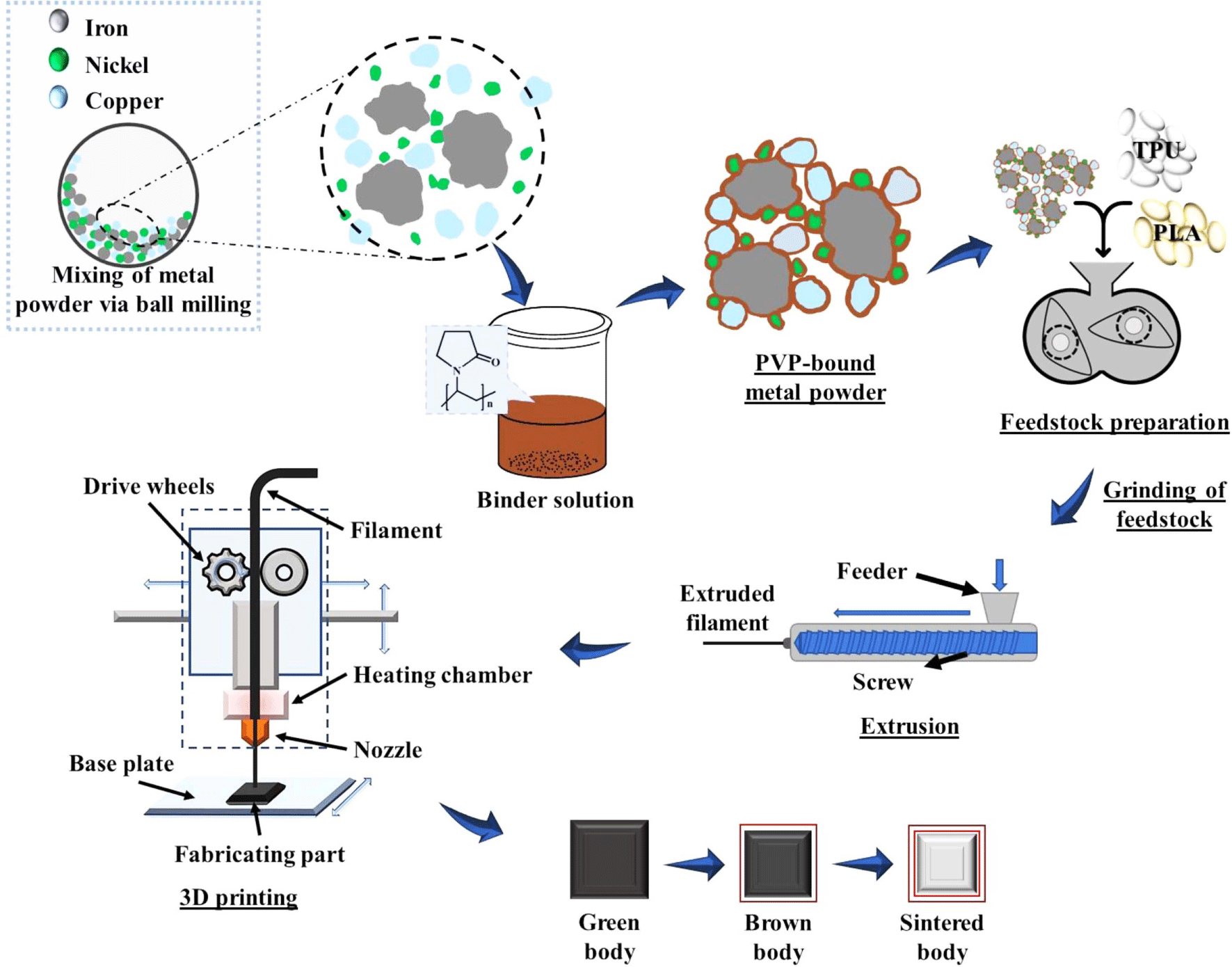
The Fe and other alloying elements were weighted according to the composition Fe1.5Cu1.5Ni (by wt.%) and uniformly mixed via a ball milling process without a ball for 5 hours with the speed of 400 rpm. Next, a PVP binder of 0.5 wt.% was thoroughly mixed in ethanol using a magnetic stirrer. Next, the metal powder mixture was incorporated into the PVP solution and mixed using a mechanical stirrer until the solution became a thick paste. The prepared solution was dried at 60°C in a hot air oven to remove the solvent (ethanol) from the solution. Finally, the PVP-coated metal powders were smashed and pulverized using mortar and pestle and filtered through a 30 mesh (i.e., 600 μm) fine sieve to procure PVP-bound metal powders.
The feedstock was prepared by melt mixing of polymer carrier and PVP-bound metal powders. Two carriers, TPU and PLA, in a ratio of 9:1 (by vol.%) respectively, are homogeneously mixed with 45 vol.% of PVP-bound metal powders using an internal mixer with a chamber volume of 160 cm3. Initially, the polymer carrier TPU and PLA (9:1 by vol.%) were mixed at 160°C with a rotors speed of 25 rpm for 5 minutes to produce a uniform polymer blend. After that, the PVP-bound metal powders were gradually introduced into the mixing chamber for 20 min. The mixing parameters such as temperature, rotors speed, and mixing time were optimized and set after ensuring the well-fitted mixing condition. The obtained metal-polymer feedstock was further ground into a small and fine size by the grinder. Finally, the ground feedstock was used for the fabrication of metal-polymer filaments.
The metal-polymer filaments for 3D printing were prepared by introducing the prepared feedstock into a single screw extruder (Filabot EX2) with a 1.75 mm nozzle diameter and 14 rpm screw speed. The filaments were prepared at varying extrusion temperatures (160, 170, 180, and 190°C) to optimize the processing condition of filament fabrication for 3D printing. Then, the extruded filament was passed through the Filabot airpath to cool the filament and collected using a spooler.
The FDM process of metals-polymer filament samples was performed using a Rokit desktop 3D printer (Rokit, South Korea). The obtained filament was passed through a 3D printer-hardened brass nozzle with a nozzle temperature of 210°C and a diameter of 1.0 mm. The nozzle temperature and diameter were optimized and set to achieve the best quality 3D printed object. The nozzle diameter smaller than 1.0 mm of the 3D printer tends to form filaments clogging. Therefore, a fully dense infill (i.e., 100%) with a layer height of 1.0 mm and a linear infill pattern was used while preparing 3D-printed objects. The printing speed and bed temperature were fixed to 10 mm·s-1 and 60°C, respectively, resulting in better infill, consistent material flow, and good adhesion. The final cube-shaped 3D printed object took around 15 min and 0.587 m of filament to print. All the input printing parameters were modeled using NewCreatorK slicing software.
The thermal debinding of 3D printed cube object was performed at three different temperatures, i.e., 600, 800, and 1000°C, under Ar (argon) gas atmosphere to remove the organic compounds. Two different heating rates (0.1 °C/min and 0.2 °C/min) were used in thermal debinding to optimize process parameters for procuring the best 3D samples for sintering. After debinding (brown body), the sintering process was directly performed on completely debound cubic-shaped samples under a high vacuum atmosphere (below 5.0×10⁻⁷ torr) and 600 MPa pressure at 1350°C. The sintering process was accomplished with a heating rate of 10°C/min for 5 hours.
Feedstock was prepared with PVP-bound metal powders 45 by vol.% and polymer 55 by vol.% (TPU + PLA). A single screw extruder extruded the filament from the feedstock. The 3D-printed object was produced from the filaments using an FDM printer. Finally, the thermal debinding followed by the sintering process removed the binder and achieved a dense product. The overall process is schematically presented in Figure 1.
The morphology of PVP-bound metal powder was studied using optical microscopy (DIM-03; Alfa Mirage Co., Ltd). The SEM analysis investigated the microstructural variation, porosity, and elemental distribution of 3D printed objects during the debinding and sintering processes. The thermogravimetric analysis (TGA) (Q500; TA Instruments Co., Ltd) was used to investigate the thermal property. XRD analysis was performed using an X-ray diffractometer (XRD: Bruker D2 phaser) under a CuKα radiation source to understand the stability of metal powder in its elemental state, types of phases, and compounds formed during sintering.
Results and Discussion
This study focuses on a multi-component binder system that facilitates the fabrication route from feedstock preparation and 3D printing to debinding and sintering. Therefore, this section discussed the binder formulation, shaping, debinding, and sintering with optimized process parameters to obtain a highly dense sintered sample. Thermal debinding is performed at different temperatures with varying heating rates to remove the binder polymer and examine the neck growth in a 3D-printed structure. SEM analysis and EDX spectra confirmed the microstructural phase transition and the elemental composition of the 3D cubic structure.
PVP as a binder acts as a robust and efficient stabilizer and a dispersant.28,29Figure 2 shows the optical microscopy images of steel alloy powders mixture of Fe-1.5Cu-1.5Ni (by wt.%), mixed using a ball milling process (5 hours at 400 rpm) with and without a PVP binder. Figure 3 presents the optical microscopy images of the metal-polymer filaments produced using a single screw extruder at different temperatures. It is seen from Figure 2(a) that the ball-mill processed metal powder mixture without binder showed a random distribution of small metal particles. However, in the case of PVP-bound metal powders, the PVP binder stabilized the metal particles by coating over the surface of the particle and adhering to the bigger size, as shown in Figure 2(b).18


Further, the internal mixer mixes the PVP-bound metal particles with TPU/PLA blend. During mixing, the PVP binder acts as a dispersant and facilitates cluster-free dispersion of metal particles inside the carrier polymer.26 The PVP binder showed the tertiary amide and polar groups that assist the uniform dispersion of the particle and attract the metal ions due to their strong affinity. The homogenous composition and strong interactions of PVP-bound metal particles with the polymer blend provided continuous flowability and flexibility to the filaments. However, the extruder temperature also played a significant role in preparing high-quality filaments.30 Results revealed that the extruded filament was not collected by the spooler due to very slow extrusion at a lower temperature (160°C). While, at 170°C, the extruded filament showed the best surface quality, as confirmed by the optical microscopy image in Figure 3(a). The surface of the filament was smooth without any gross defects. The surface was covered with polymer blend and metal powders with strong interfacial bonding contributing to the excellent filament flexibility during handling and feeding through the 3D printer. However, at higher temperatures (i.e., 180 and 190°C), the surface quality of the filament deteriorated due to the thermal degradation of the polymer blend during the extrusion process, as shown in Figures 3(b and c).18 Therefore, the best quality metal-polymer filament was fabricated at 170°C temperature for 3D printing, offering a 1.75 ± 0.5 mm diameter measured by a micrometer.31 The prepared filament was further used for the 3D printing of a cubic-shaped 3D structure.
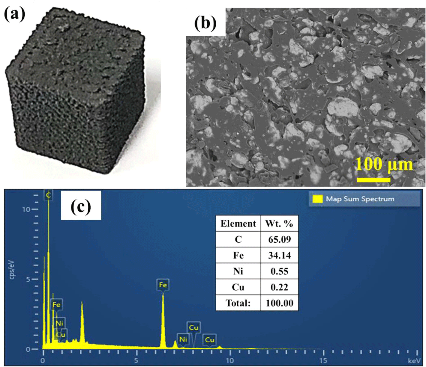
The high-quality metal-polymer filament of 1.75 ± 0.5 mm diameter was used for preparing a 3D cubic structure using a 3D printer with a nozzle diameter of 1.0 mm and a temperature of 210°C. The nozzle diameter and temperature, printing speed, and bed temperature of the 3D printer were identical for all specimens to achieve a high-quality 3D cubic structure. The nozzle temperature was set above the melting temperature of the polymer for better filament extrusion by lessening the viscosity.32Figure 4 shows the SEM images and EDX spectra of the prepared 3D printed structure. The 3D cubic structure, as shown in Figure 4(a), confirmed the best quality of the printed object with minimum surface defects and cracking. The SEM images of the 3D cubic structure, as shown in Figure 4(b), revealed the successful distribution of PVP-bound metal particles inside the TPU and PLA blend. The SEM images displayed the strong interfacial interaction of PVP-bound metal particles with the TPU/PLA blend, which provides a uniform shape, flexibility, and sufficient mechanical strength to the prepared 3D structure. The EDX spectra of SEM images, as shown in Figures 4(c), confirmed the presence of all the alloying elements and polymers in the 3D structure. The EDX pattern displayed the highest amount of polymer content, i.e., 65.09 (C-content), followed by Fe, Ni, and Cu in weight percentages of 34.14, 0.55, and 0.22% in a 3D cubic structure, respectively.
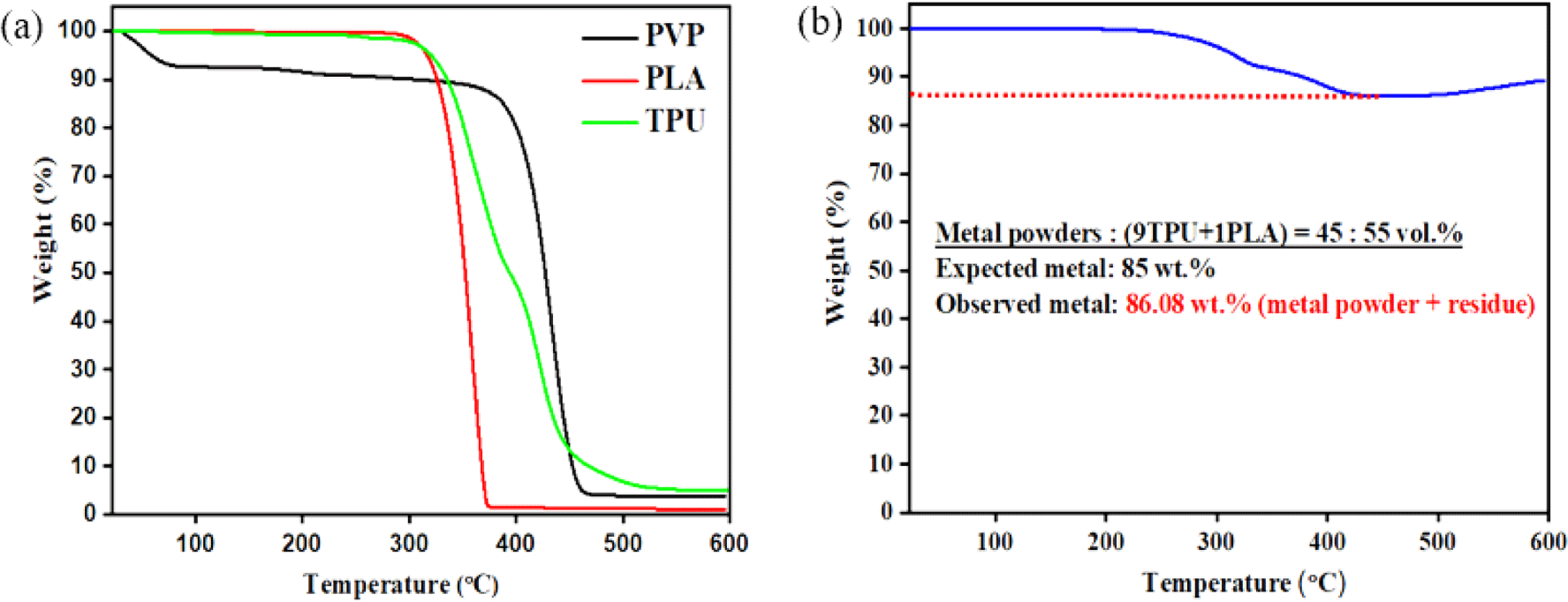
After 3D printing, removing the multi-component binder systems from the 3D cubic structure is highly recommended for developing the desired steel alloy specimens for sintering. The binder system can be removed by debinding the 3D cubic structure at a higher temperature18,32 (above decomposition temperature). Therefore, examining the thermal behavior and decomposition temperature of the multi-component binder systems and the metal powder-filled polymer becomes necessary before thermal debinding. Figure 5 shows the thermogravimetric analysis of a multi-component binder system and metal powder-filled polymer from room temperature to 600°C. Figure 5(a) presents the weight loss versus temperature curve of PVP, PLA, and TPU polymers. Results revealed that the decomposition in PLA and TPU was initiated at 300°C and fully decomposed at 373°C and 480°C, respectively. For the PVP binder, the initial weight loss from 100 to 90% at 80°C was mainly due to the removal of the moisture content present in the PVP binder. At the same time, the actual decomposition started at 360°C and fully decomposed at 460°C. However, in Figure 5(b), the weight loss versus temperature curve showed that the metal powder-filled polymer was thermally stable up to 270°C; after that, it is fully decomposed at 420°C. However, it is noted that the metal powder-filled polymer shows a maximum weight loss of up to 86.08 wt.%, which includes 85 wt.% of metal powders (expected) and the remaining 1.08% carbon residue formed due to the decomposition of multi-component binder system at 420°C.
After TGA analysis, it was confirmed that the debinding temperature should be 600°C to remove the multi-component binder system from the 3D printed structure. Therefore, the thermal debinding was performed at three different temperatures, i.e., 600, 800, and 1000°C, with two different heating rates (0.1°C/min and 0.2°C/min) to optimize the process parameters and to prepare the desired specimen for sintering.33,34Figure 6 shows the SEM images and EDX spectra of the surface of the thermally debound cubic structure obtained at 600, 800°C and 1000°C with a heating rate of 0.1°C/min. The SEM image of the thermally debound sample at 600°C (Figure 6(a)) indicates the presence of a binder system on the metal powder surfaces. The binder system holds the metal particles and agglomerates them into large, clustered sizes. The multi-component binder system is not entirely removed and the C-content is available in an optimal amount, i.e., ~50 wt.%. After increasing the debinding temperature to 800°C, as shown in Figure 6(b), the metal particles are mechanically stable and reorganized. The EDX spectra revealed the presence of C, Fe, Cu, and Ni in the debinding structure. The weight percentage of C-content was reduced to 27.36 wt.%, and Fe-content increased from 47 to 70.71 wt.%, as confirmed by the EDX spectra. The C content (~27.36 wt.%) proved the binder polymer inside a 3D structure after thermal debinding at 800°C. The homogeneous mixing of metal particles in a multi-component binder system facilitated the metal particles in capturing the free radicals induced during the pyrolysis of the binder polymer. Therefore, it was required to increase the debinding temperature to 1000°C to remove the binder polymer. Figure 6(c) shows the SEM image and EDX analysis of the thermally debound sample prepared at 1000°C. The SEM image confirmed the development of neck growth between the Fe alloy metal particles. Results revealed the complete removal of binder polymer content from the 3D printed structure after debinding at 1000°C. During thermal debinding, the binder polymer started degradation and flowed to the outer surfaces by the convection and diffusion process.35,36 EDX spectra displayed the uniform distribution of Fe, Cu, and Ni elements with enrichment of the Fe content (~94.98 wt.%) and a very low wt.% of C-content (~3.86) followed by Ni (~0.36) and Cu-content (~0.80) in the 3D cubic structure.
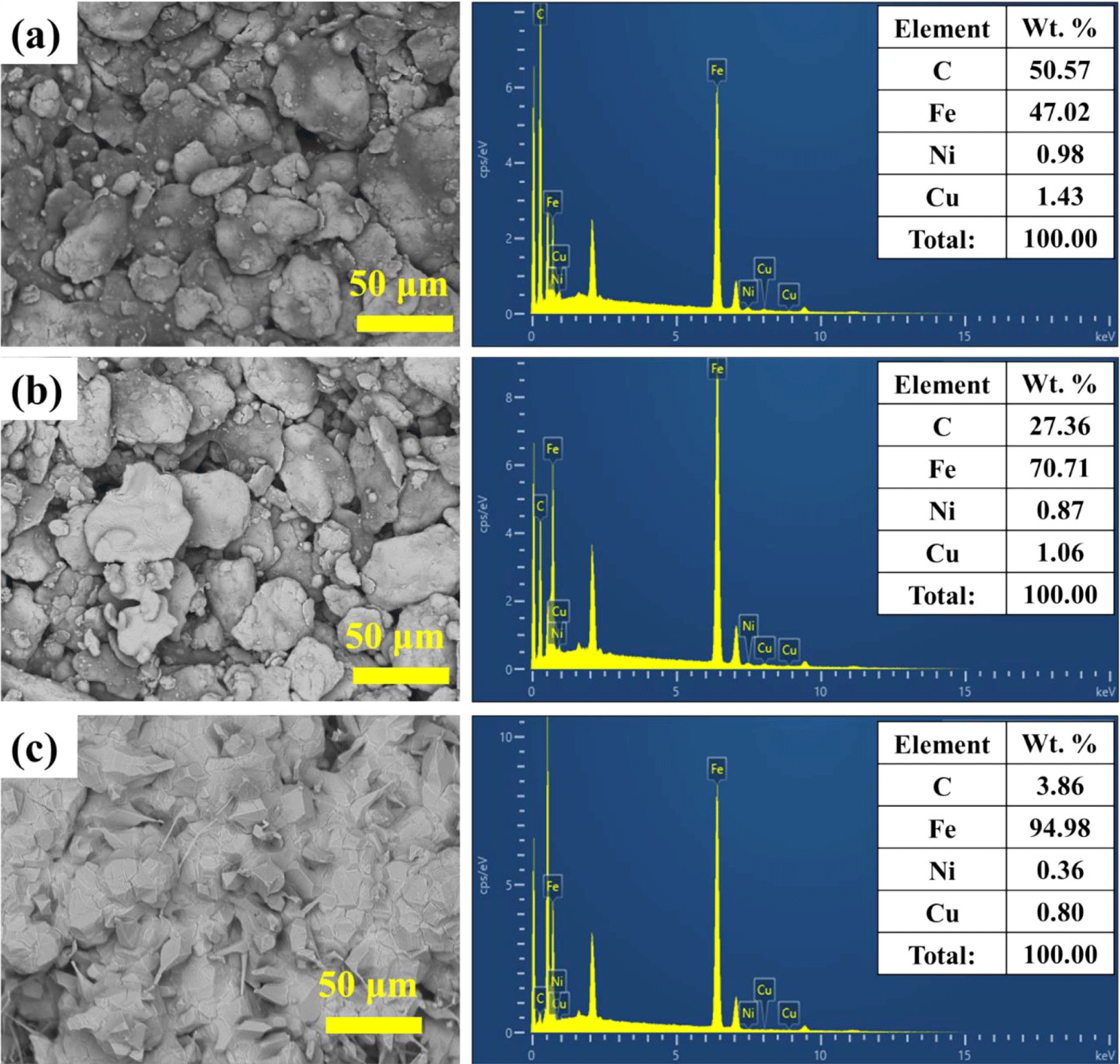
Figure 7 shows the thermally debound and sintered sample images of 3D structures prepared at different temperatures and heating rates. Figures 7(a, b, and c) present the debound sample images at 600, 800, and 1000°C with a heating rate of 0.1 °C/min. These images confirmed that the surface quality of the samples at varying temperatures remained the same; however, the sample color changed from black to dark grey due to the removal of C-content at a higher temperature. Nevertheless, by increasing the heating rate to 0.2 °C/min on 1000°C debound samples, as shown in Figure 7(d), the sample indicated the surface defects such as blistering and distortion. This revealed that the variation in heating rate affects the surface properties of the thermally debound specimens. The risk of blistering and distortion during thermal debinding was successfully decreased at a slow heating rate (approximately ~0.1 °C/min).33
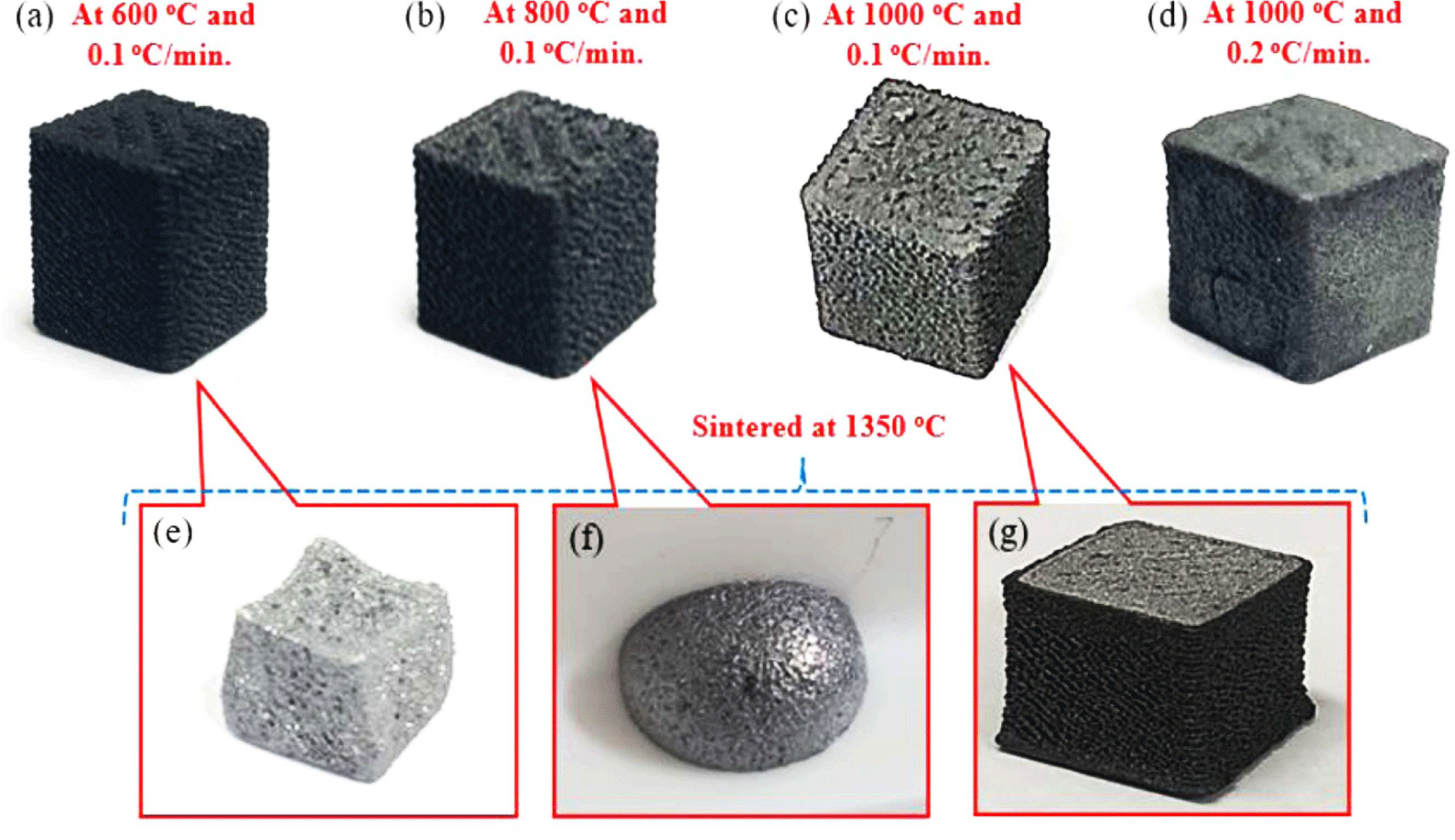
After thermal debinding, sintering was performed on debound samples at 1350°C with a heating rate of 10 °C/min for 5 hours in a vacuum furnace to avoid oxidation from the surfaces. During sintering, the structure of prepared thermally debound samples (at 600 and 800°C) was damaged and distorted due to the high heating rate and high sintering temperature, as shown in Figure 7(e and f). However, in the case of a debound sample produced at 1000°C, after sintering, the 3D structure became dense and in perfect shape (Figure 7(g)).36 Furthermore, the anisotropic shrinkage as a function of build orientation was calculated to examine the dimensions of 3D printed, debound, and sintered structures. Figure 8 depicts the anisotropic shrinkage in the 3D printing structure during thermal debinding and sintering. The average shrinkage in the X, Y, and Z-direction was estimated as 15.8, 15.8, and 16.0%, respectively. This anisotropic behavior was attributed to the layer-by-layer approach used for 3D printing using the FDM process. The selection of process parameters during 3D printing, such as build orientation, part geometry, and flow patterns, can alter the volumetric anisotropic shrinkage and consequently affect the final dimensions of the sintered parts.37-39
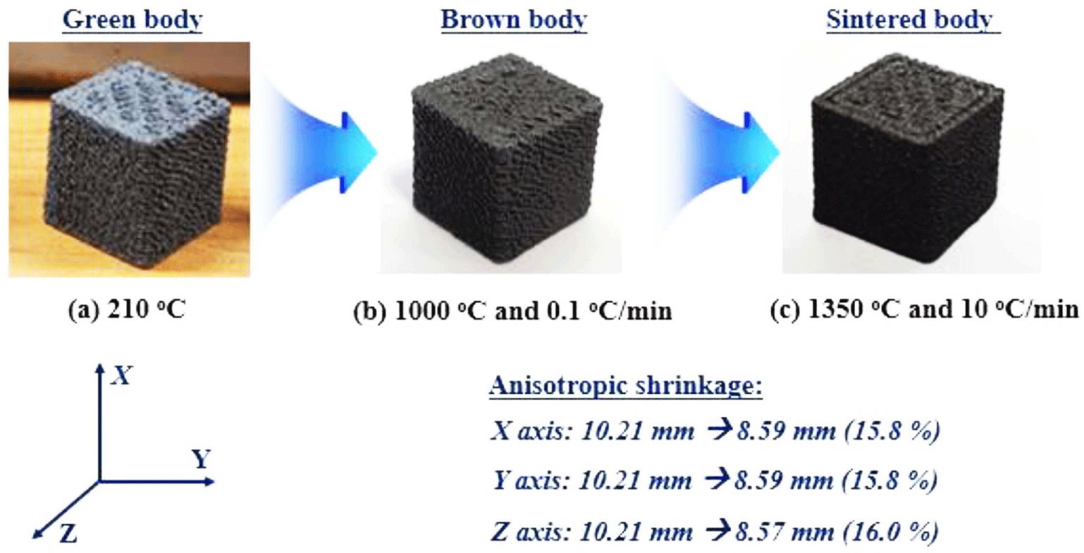
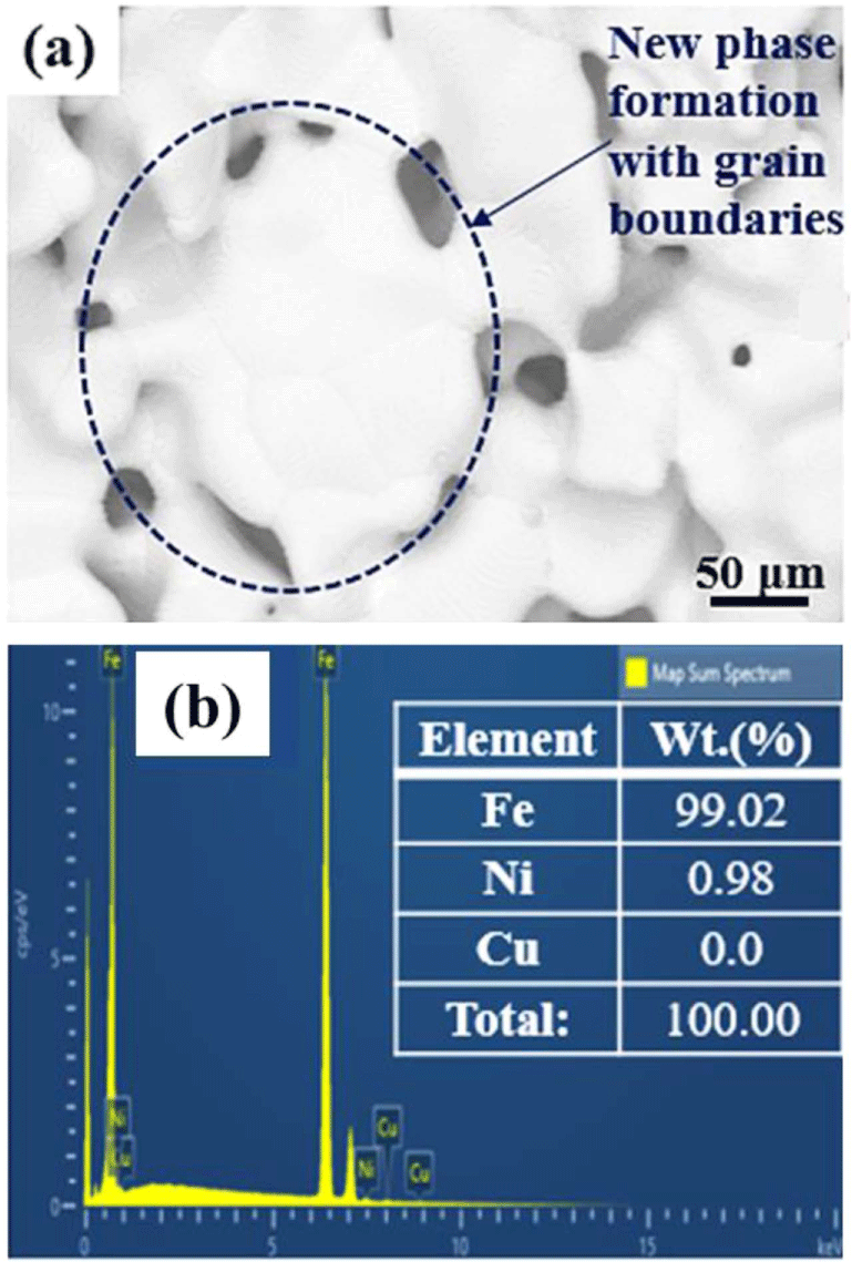
Figure 9 shows the SEM image and EDX spectra of the 3D sintered structure. As shown in Figure 9(a), the SEM image revealed the formation of a new phase along with the grain boundaries. The sintering at 1350°C enhanced the grain growth, as confirmed by the SEM image. The long sintering time directs to no further densification but larger grain sizes.40,41 EDX pattern confirmed the elemental composition of steel alloy in the obtained sintered structure. The carbon residue was removed due to the higher heating rate during sintering.40,42 The enrichment of Fe-content to 99.02 wt.% and disappearance of the Cu-content were due to the formation of a new super saturated Fe structure; however, Ni content was available to 0.98 wt.%.
Figure 10 shows the schematic representation of the morphology of the 3D printed, thermally debound, and sintered structure of steel alloy. The morphology of the 3D printed structure shows that the multi-component binder system strongly holds the metal particles with good interfacial bonding by providing strength and stiffness to the structure.15,43,44 While thermal debinding at 600 and 800°C with a heating rate of 0.1 °C/min, the binder system is not entirely removed and some carbon residues remains due to less porosity and the presence of metal particles that captur free radicals during pyrolysis. However, at 1000°C debinding temperature, the carbon residue reduces to a large extent, and the fusion between metal particles is initiated by developing neck growth from metal particles. During sintering at 1350°C, the metal particles are completely fused, and a new microstructure with grain boundaries of steel alloy is formed.
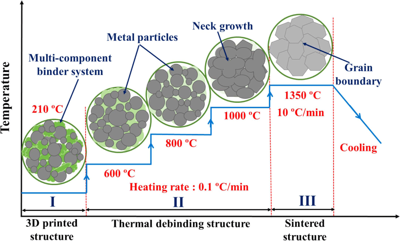
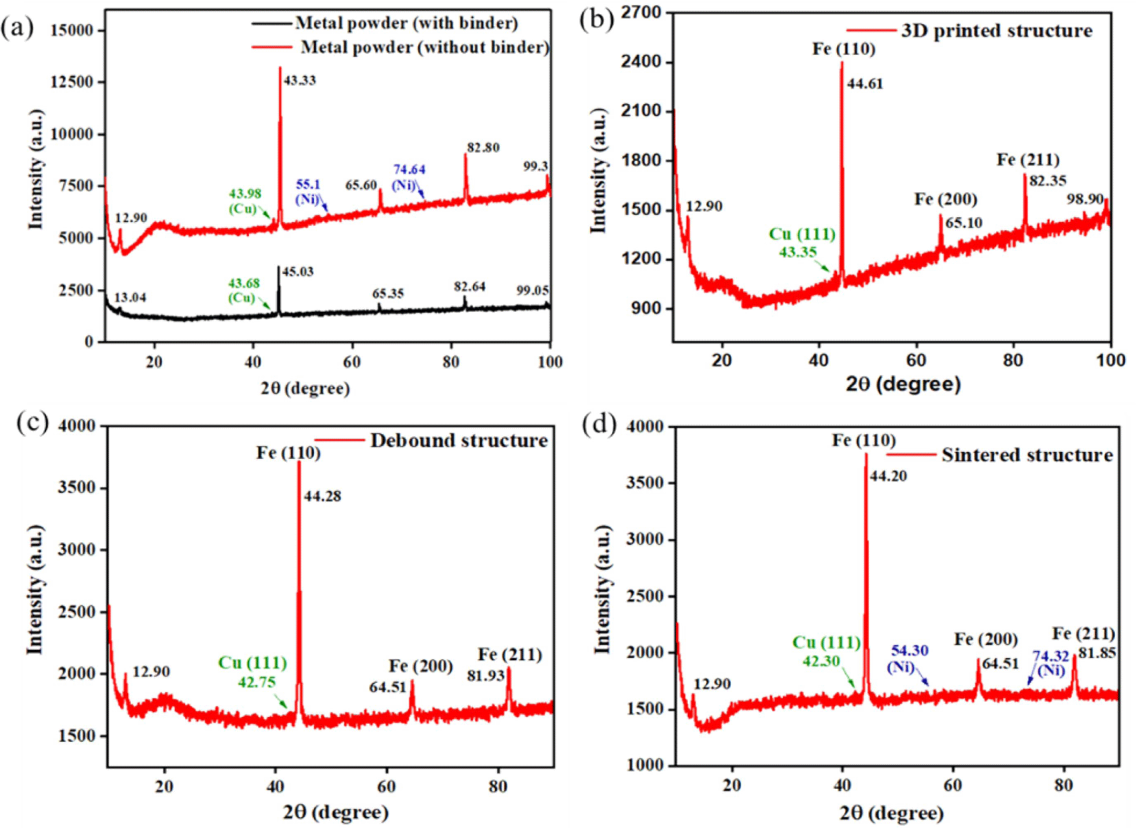
Figure 11 shows the XRD pattern of metal powder with and without binder, 3D printed, debound, and sintered structure. The XRD pattern of metal powder with and without binder confirmed the presence of metal powders, i.e., Fe (2θ value of 43.33°, 65.60°, and 82.80°), Cu (43.98°) and Ni (55.1° and 74.64°).45Figures 11(a) and (b) revealed the presence of polymer binder over the surface of the metal particle reduced the intensity of the metal particles. The three sharp peaks in the XRD pattern correspond to the (110), (200), and (211) planes of Fe, and a very short peak (111) corresponds to Cu, respectively.46,47 Results revealed that the Fe component possessed a high degree of crystallinity and the corresponding peaks of Cu and Ni reduced their intensity and disappeared completely, as shown in Figures 11(c) and (d). Cu peak at 2θ value of 43.98° disappeared utterly, indicating the formation of the fcc supersaturated Fe (Ni) due to the Ni atomic penetration into the substitution sites of the Fe lattice.
Conclusions
A novel multi-component binder system using PVP as a binder and TPU and PLA as a carrier was successfully developed. The PVP binder bound steel alloy powders using the ball milling process, and the bound metal particles were mixed with TPU and PLA blend in the proportion of 45:55 vol.% through the internal mixer. The PVP binder acted as a stabilizer and dispersant and facilitated cluster-free dispersion of metal particles inside the carrier polymer. The high-quality filament has been prepared using TPU-PLA composite as a carrier which was confirmed by optical microscopy. The use of PLA along with TPU helped to increase the surface property of the filament. The dispersion and interaction of PVP-bound metal particles with TPU and PLA blend became the primary feature in developing high-quality filament. The FDM technique processed the prepared filament, and the obtained 3D-printed cubic structure had no visible surface defects, as confirmed by the SEM images. Optimizing thermal debinding was done at different temperatures (600, 800, and 1000°C) and heating rates (0.1 and 0.2 °C/min). Thermal debinding at 1000°C and 0.1 °C/min heating rate showed the best result with neck growth formation between Fe-alloy components.
Further, sintering was successfully performed at 1350°C with a heating rate of 10°C/min for 5 hours, and the result revealed the formation of a new phase along with the grain boundaries in the sintered sample. Hence, these investigations offer an insight into the structure-property relation needed to make processable filaments of steel alloy feedstocks for FDM combined with thermal debinding and sintering. Thus, it can be the basis for the applicability of this manufacturing strategy for other metallic materials.


